
Force measuring speculum

Inactive Publication Date: 2019-04-11
UNIV OF UTAH RES FOUND
View PDF0 Cites 0 Cited by
  • Summary
  • Abstract
  • Description
  • Claims
  • Application Information

AI Technical Summary

Benefits of technology

The present invention is about a device that measures the strength of muscles in the pelvic floor. The invention includes a sensor that can be detached from the device and replaced for future use while the contaminated part is sterilized. This helps to maintain the device's cleanliness and prevents contamination between patients. The device can also be used multiple times, which makes it more durable and reduces associated costs.

Problems solved by technology

These disorders are caused by weakening of the muscles that line the bottom of the abdominal cavity, and can lead to urinary incontinence, fecal incontinence, and pelvic organ prolapse.
Inability of the pelvic floor muscles to support the abdominal organs can lead to pelvic floor symptoms, such as urinary incontinence due to lack of support at the bladder neck (DeLancey et. al.
Digital palpation is inexpensive and simple, but digital palpation is a subjective measure, and has been shown to have poor reliability for pelvic floor muscle force evaluation (Bo and Finckenhagen (2001), “Vaginal palpation of pelvic floor muscle strength: inter-test reproducibility and comparison between palpation and vaginal squeeze pressure” Acta Obstetricia et Gynecologica Scandinavica, 80: 883-887).
This can complicate the post-measurement reprocessing of the force measuring device.
Devices undergoing reprocessing are subjected to extreme environmental conditions, such as heat, humidity, and chemicals.
Typical sensing elements used on conventional force measuring devices cannot withstand such conditions and will typically fail after a few reprocessing cycles, severely limiting the usefulness of the devices and making it difficult for clinicians to justify purchasing such devices.

Method used


Image

  • Force measuring speculum
  • Force measuring speculum
  • Force measuring speculum

Examples


Embodiment Construction

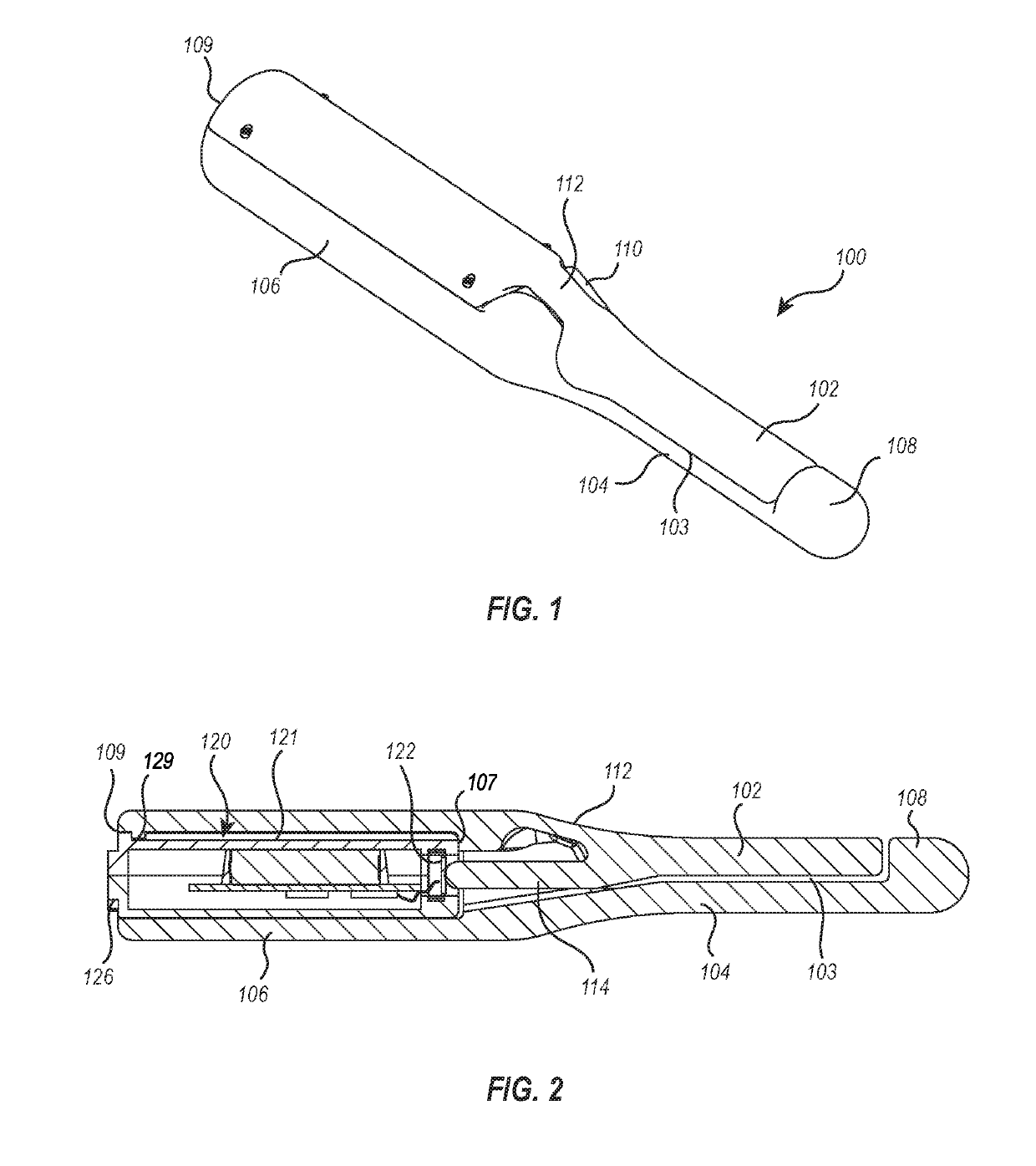
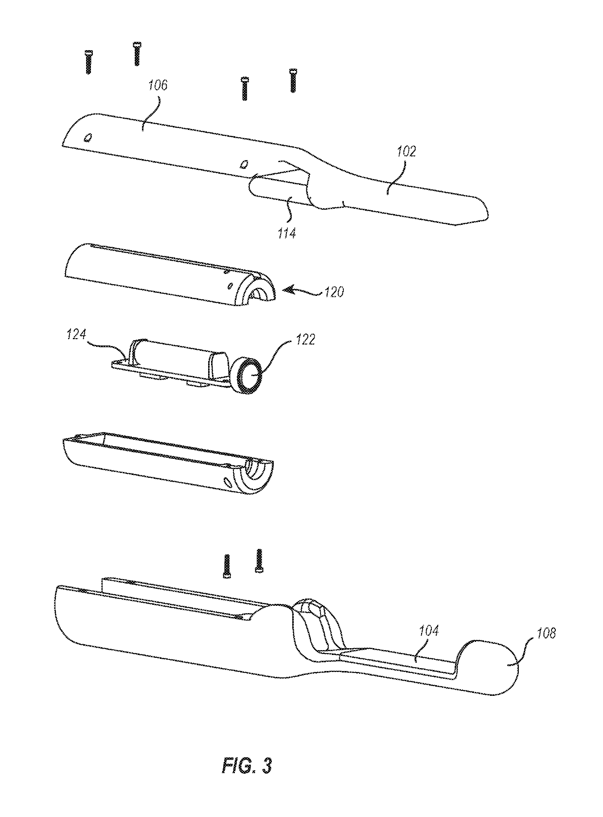
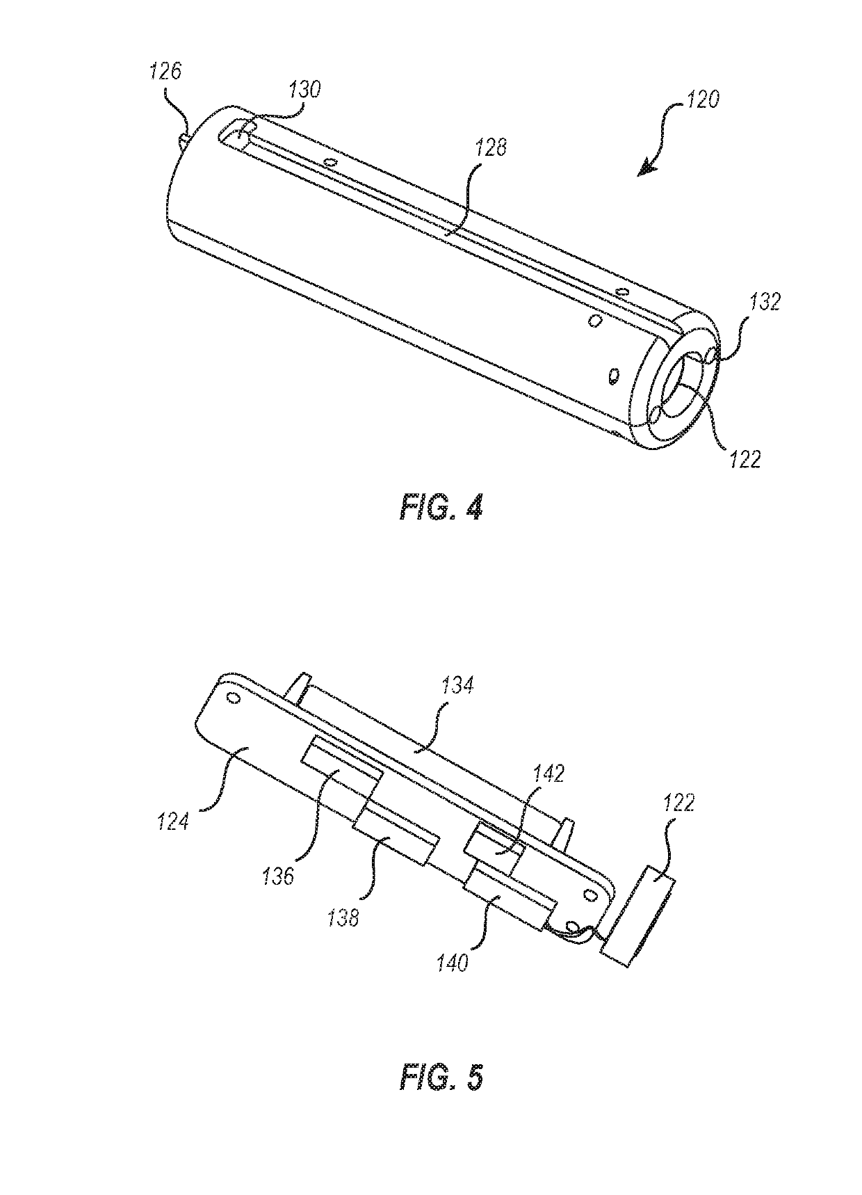
[0026]FIG. 1 illustrates an exemplary embodiment of a force measuring speculum device 100 in isometric view. The device 100 is also shown in cross-section in FIG. 2 and in an exploded view in FIG. 3. The device 100 includes a bill assembly including a first bill 102 and an opposing second bill 104. A gap 103 is defined between the first and second bills 102, 104. The bills 102 and 104 each extend between a proximal end and a distal end. The proximal ends of each of the bills 102 and 104 converge to form a handle 106.

[0027]In this embodiment, an upper portion of the handle 106 is integrally formed with the first bill 102 and a lower portion of the handle 106 is integrally formed with the second bill 104. This arrangement allows the device 100 to be readily assembled by fastening the upper and lower portions together. In other embodiments, however, one or both of the bills 102, 104 are not necessarily integrally formed with portions of the handle 106, and may be mechanically fastened ...


PUM


Abstract

The present disclosure relates to a speculum device for measuring pelvic floor muscle (PFM) contractile forces. The speculum device includes a first bill and a second, opposing bill. Each bill has a proximal end attached to a handle. The handle includes a housing in which a sensor cassette may be selectively inserted. When inserted, the sensor cassette can measure contractile forces applied to the upper and lower bills and mechanically transferred to the sensor cassette. The sensor cassette does not come into contact with the patient while measurements are taken. Afterwards, the sensor cassette may be removed from the housing while the remainder of the device is sterilized.

Description

CROSS-REFERENCE TO RELATED APPLICATIONS[0001]This Application claims priority to and the benefit of U.S. Provisional Patent Application No. 62 / 570,010, filed on Oct. 9, 2017 and titled “Force Measuring Speculum,” the entirety of which is incorporated herein by this reference.BACKGROUND[0002]Pelvic Floor Disorders (PFDs) affect nearly one in four women in the United States (Nygaard, Ingrid et al. “Prevalence of Symptomatic Pelvic Floor Disorders in US Women.” JAMA: the journal of the American Medical Association 300.11 (2008): 1311-1316). These disorders are caused by weakening of the muscles that line the bottom of the abdominal cavity, and can lead to urinary incontinence, fecal incontinence, and pelvic organ prolapse. The pelvic floor muscles form a hammock-like supporting structure for abdominal organs. Inability of the pelvic floor muscles to support the abdominal organs can lead to pelvic floor symptoms, such as urinary incontinence due to lack of support at the bladder neck (D...

Claims


Application Information

Patent Timeline
IPC IPC(8): A61B5/22A61B5/00A61B1/303
CPCA61B1/303A61B2562/0261A61B5/227A61B5/6885
Inventor COTTLE, BRIAN K.HITCHCOCK, ROBERT W.NIEDERAUER, STEFAN JULIUS
Owner UNIV OF UTAH RES FOUND
Learn More