Wheeled Walker Wheel Direction Lock Apparatus and Method

Active Publication Date: 2019-04-11
FIRSTSTREET FOR BOOMERS & BEYOND INC
View PDF5 Cites 8 Cited by
  • Summary
  • Abstract
  • Description
  • Claims
  • Application Information

AI Technical Summary

Benefits of technology

[0019]It is an advantage of the invention that a movable seat may be provided to facilitate an ample walking space inside the walker footprint when the seat apparatus is moved forward to the anterior walking position, and to allow the user to sit down and rest when the seat apparatus is moved backward to the posterior sitting position.
[0020]It is another advantage of the invention that the wheeled walker apparatus may be converted to a transport chair apparatus by locking the wheel direction lock for the front wheels to cause the front wheels to move in straight line, releasing the wheel direction locks for the rear wheels to allow the rear wheels to turn freely, and sliding the movable seat to the posterior sitting position to receive a seated user. In this way the apparatus may be pushed by a helper from the front side to move the apparatus in approximately rearward direction.
[0021]It is yet another advantage of this invention that all wheels ma

Problems solved by technology

However, such an assistive device has many well-known disadvantages.
One notable disadvantage is that the user needs to extend her of his hands downward to grasp the handles to support her or his body weight, so relatively significant hand and arm strength is needed to operate and maneuver the device.
Moreover, such posture may increase the risk of tipping forward when encountering terrain obstacles.
But the disclosed seat constructed between the right and left side frames blocks the space available inside the walker footprint.
After walking for a distance when the user feels tired and wants to sit down to take a rest, the device does not provide such a seat.
Disadvantageously, when the space inside the walker footprint is occupied by such a seat, the user is obliged to step behind the walker footprint and to lean over to reach the walker handles, thus an unhealthy walking posture.
Disadvantageously, such a seat is not permanently attached to the walker and the necessary mounting and unmounting proces

Method used


Image

  • Wheeled Walker Wheel Direction Lock Apparatus and Method
  • Wheeled Walker Wheel Direction Lock Apparatus and Method
  • Wheeled Walker Wheel Direction Lock Apparatus and Method

Examples


Example

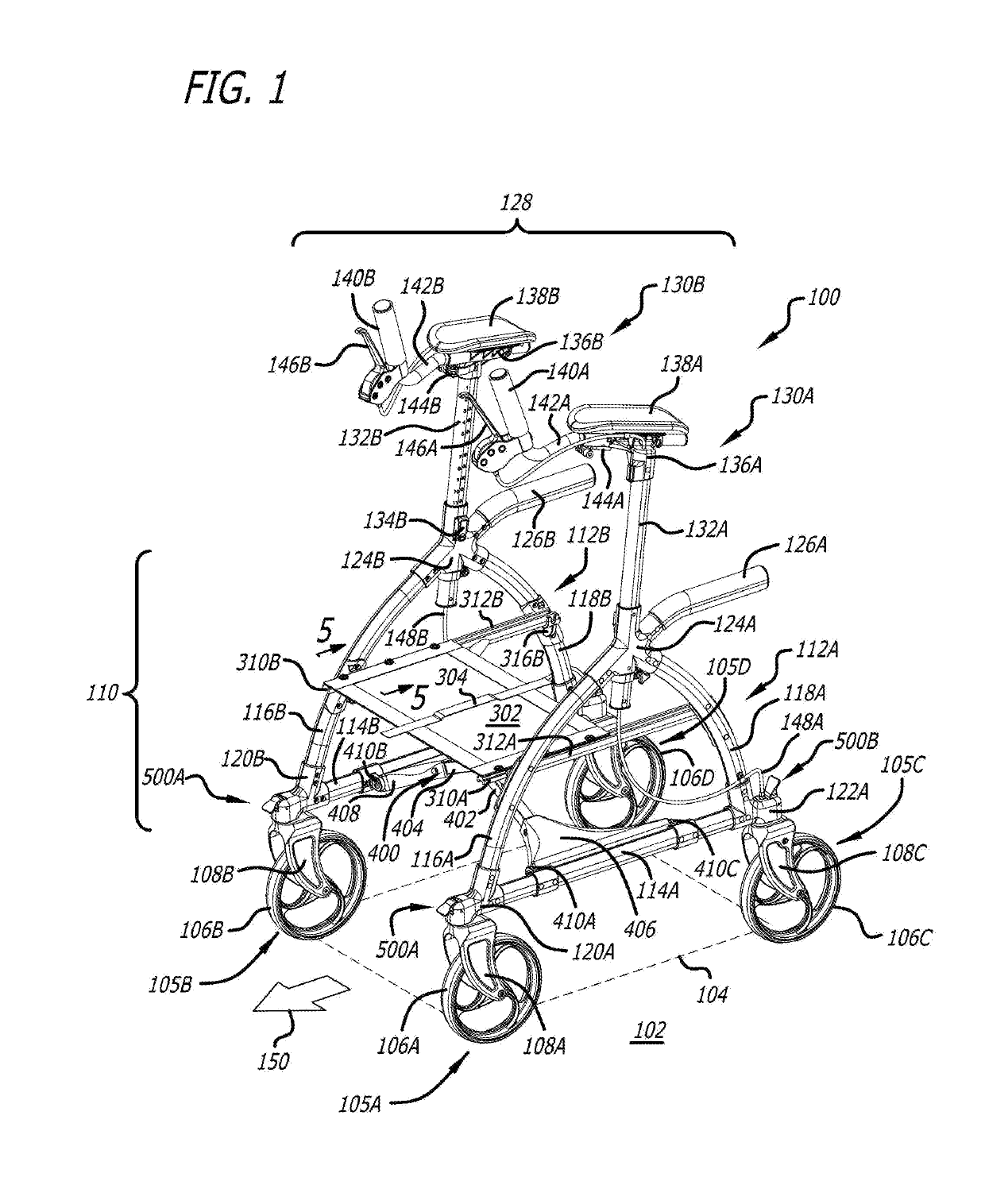
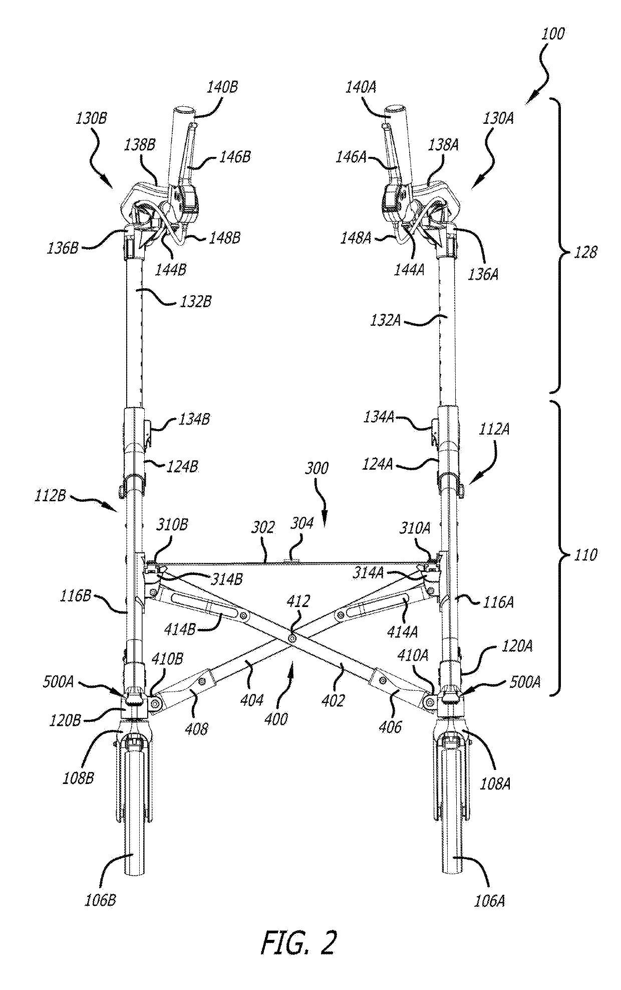
[0043]FIG. 1 shows an embodiment of a wheeled walker (or rollator) apparatus 100 in the open state on a walking surface 102 ready to receive a user 700 (FIG. 16) to operate and move along moving direction 150. Wheeled walker apparatus 100 has a frame 110 supported on walking surface 102 by four wheel assemblies 105A-D. Frame 110 includes a left side frame 112A and a right side frame 112B, each having three side frame tubes, including a respective frame horizontal tube 114A-B, a respective frame front tube 116A-B, and a respective frame rear tube 118A-B. The three side frame tubes of each side frame 112A-B form an approximately triangular shaped frame, and are connected by three respective joints, including a frame front joint 120A-B, a frame rear joint 122A-B, and a fame top joint 124A-B. For better stability, the front tubes 116A-B and rear tubes 118A-B are curved outward. On the rear end of each side frame 112A-B is attached a lower handle 126A-B.

[0044]As constructed, frame 110 fo...


PUM


Abstract

A collapsible Wheeled Walker with two side frames and two height adjustable upper body supports. The apparatus includes a plurality of wheel direction locks each coupled to a wheel and adapted to lock the wheel in fixed moving direction or to release the wheel to turn freely. The apparatus may include a seat that is slidably attached to the two side frames and is movable between a front position for walking inside the frames and a rear position sitting. The apparatus may be converted to a transport chair by locking front wheel and releasing the rear wheels, and sliding the movable seat to the rear position. It may include an X-folder that facilitates collapsing the Walker to a small footprint. It may also include two forearm gutters as part of the upper body supports that give the user an upright walking posture for health benefits.

Description

CROSS-REFERENCE TO RELATED APPLICATIONS[0001]This application is filed under 35 U.S.C. 111(a) pursuant to 37 C.F.R. 15300 claiming the benefit under 35 U.S.C. 119(e) of U.S. Patent Application No. 62 / 569,108 filed on Oct. 6, 2017 and entirely incorporated herein by reference, and also claims the benefit under 35 U.S.C. 119(a) of Chinese Patent Application No. 201721285339.6 and Chinese Patent Application No. 201721285343.2 both filed on Oct. 6, 2017 and entirely incorporated herein by reference.BACKGROUND OF THE INVENTION1. Field of the Invention[0002]This invention relates generally to assistive mobility devices and more particularly to a collapsible wheeled weight bearing walker or rollator.2. Description of the Related Art[0003]Assistive mobility devices, including walkers rollators, are well known in the art as useful means for reducing the disadvantages of mobility impairment suffered for many different reasons by many people, permitting more efficient ambulation over distance ...

Claims


Application Information

Patent Timeline
IPC IPC(8): A61H3/04
CPCA61H3/04A61H2003/046A61H2201/1635A61H2201/0161A61H2201/0192A61H2201/1253A61H1/00A61H2201/1633A61H2201/5053A61H2203/0406A61H2201/0157A61H2201/0173A61H2203/0425A61H2003/002A61H2003/006A61H2201/164
Inventor PAN, YICHUANFELLINGHAM, PETER JAMESZHANG, ZELINPURCELL, DAVID ALLENPETERSEN, DAVID MICHAELRIEGER, SCOTT ALLEN
Owner FIRSTSTREET FOR BOOMERS & BEYOND INC
Why Eureka
Try Eureka