
Brake pad wear estimation

a technology of brake pads and wear estimation, applied in the direction of mechanical equipment, instruments, force/torque/work measurement apparatus, etc., can solve the problems of giving the vehicle operator advanced warning, mechanical scraper making an annoying high frequency noise, and gradually decreasing the thickness of the brake pad

Inactive Publication Date: 2019-04-11
GM GLOBAL TECH OPERATIONS LLC
View PDF2 Cites 14 Cited by
  • Summary
  • Abstract
  • Description
  • Claims
  • Application Information

AI Technical Summary

Benefits of technology

The patent describes a method for estimating the thickness of a vehicle brake pad by measuring the corner torque and power of the brakes. This information is used to determine the brake pad wear rate per unit of power. The brake pad wear is then estimated based on the wear rate and the corner power. The method can be used in conjunction with telematics to notify the driver of the brake pad thickness. The patent also includes a computer program product that includes instructions for implementing the method. The technical effect of the patent is to provide a reliable and accurate way to estimate the thickness of vehicle brake pads, which can help to prolong the life of the brakes and improve safety.

Problems solved by technology

The thickness of the brake pad gradually decreases as a result of wear as it is used.
The mechanical scraper makes an annoying high frequency noise, which is an unfriendly reminder that the brake pad needs to be replaced.
Although the noise does alert the vehicle operator that the brake pad is worn out, it does not give the vehicle operator advanced warning, or a continuous determination the lining thickness, only that the brake pad has worn down to a low level.
However, such sensors are typically expensive, and do not provide a continuous indication of brake pad thickness through the life of the brake pad.
Racetrack operation of a vehicle requires attention to brake pad wear, as brake pads may tend to wear more quickly under the relatively high speed maneuvering.
Also, due to different loading conditions, uneven side-to-side brake pad wear on each axle is normally seen during aggressive racetrack maneuvering.
Visually inspecting brake pads during racetrack sessions is inconvenient as “pit stop” time is extended.

Method used


Image

  • Brake pad wear estimation
  • Brake pad wear estimation
  • Brake pad wear estimation

Examples


Embodiment Construction

[0025]The following description is merely exemplary in nature and is not intended to limit the present disclosure, its application or uses. It should be understood that throughout the drawings, corresponding reference numerals indicate like or corresponding parts and features. As used herein, the term module refers to processing circuitry that may include an application specific integrated circuit (ASIC), an electronic circuit, a processor (shared, dedicated, or group) and memory that executes one or more software or firmware programs, a combinational logic circuit, and / or other suitable components that provide the described functionality.

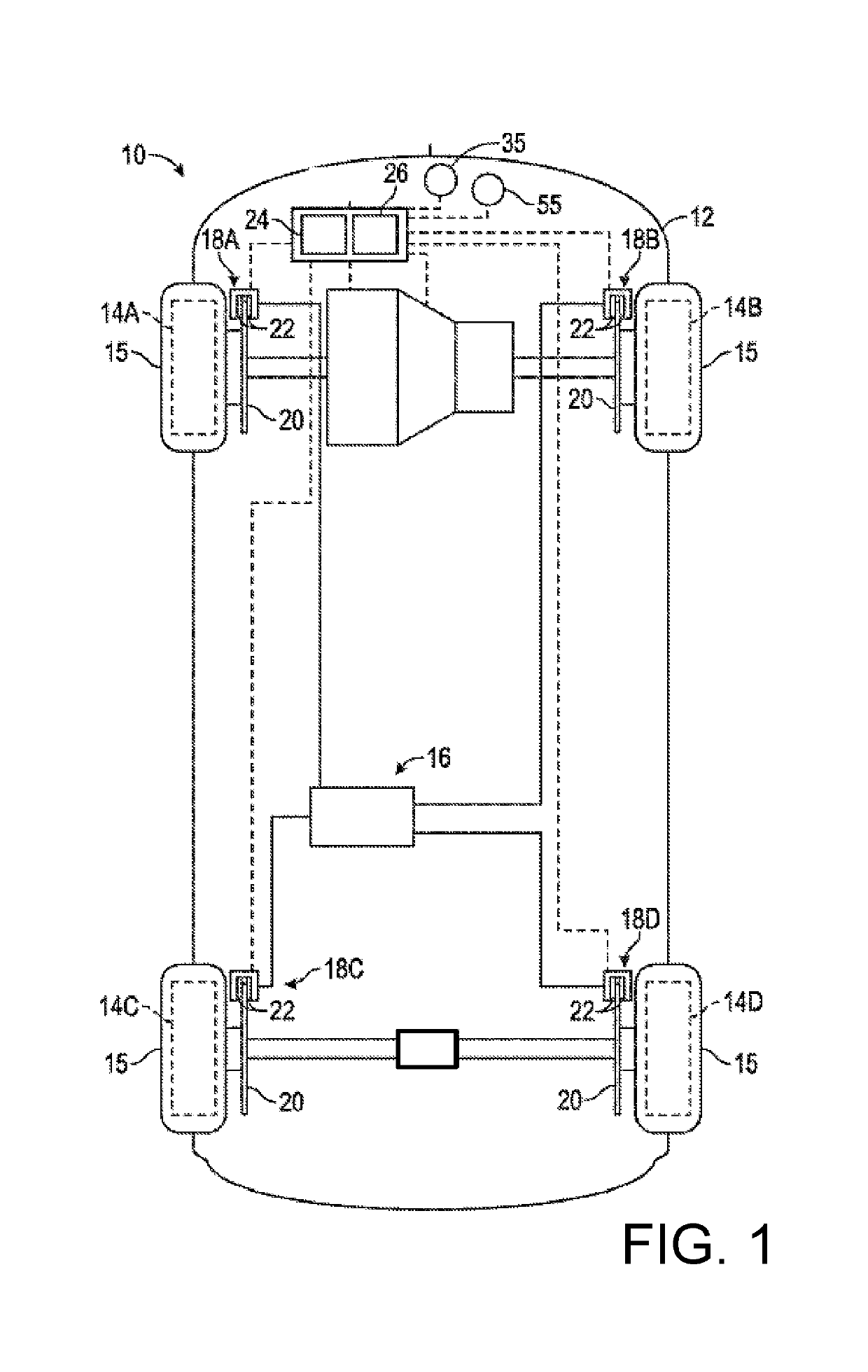
[0026]FIG. 1 shows a vehicle 10 that has a vehicle body 12 that is operatively connected to rotatable wheels 14A, 14B, 14C, 14D for moving the vehicle body 12 when propelled by an engine via a transmission. In one non-limiting example, the vehicle 10 is a front wheel-drive vehicle. A differential operatively connects the front wheels 14A, 14B, and ...


PUM

PropertyMeasurementUnit
pressureaaaaaaaaaa
corner torqueaaaaaaaaaa
temperatureaaaaaaaaaa

Abstract

Technical solutions are described for determining thickness of a vehicle brake pad. An example method for estimating brake pad wear on a vehicle includes computing a corner torque for a brake based on corner brake pressure applied to the brake. The method also includes computing a corner power for the brake based on the corner torque. The method also includes computing a rotor temperature of a rotor of the brake based on the corner power. The method also includes determining a brake pad wear rate per unit of power based on the rotor temperature and the corner power. The method also includes computing a brake pad wear based on the brake pad wear rate and the corner power.

Description

INTRODUCTION[0001]The present application relates generally to a system and method for estimating wear and, consequently, a thickness of a vehicle brake pad as it wears from use and, more particularly, to continuous blend between normal and high performance (racing) wear rates.[0002]Braking systems across multiple types of motor vehicles, are energy conversion devices which convert mechanical energy to heat. For example, disc braking systems include a non-rotating friction material and application sub-systems, as well as a brake rotor that rotates with the wheel. To stop or slow the vehicle the friction material sub-system is engaged with the braking surfaces (rotor cheeks) of the brake rotor to generate heat due to friction, thereby converting mechanical energy to heat, and slowing the rotation of the wheel.[0003]Vehicle brake pads typically last between 20,000 and 80,000 miles depending on the type of driving, i.e., city, highway, rural, etc., where the average brake pad life is a...

Claims


Application Information

Patent Timeline
Patent Type & Authority Applications(United States)
IPC IPC(8): F16D66/02G01L5/22G07C5/08
CPCF16D66/026G01L5/225G07C5/0808G07C5/0816G01L5/28F16D2066/001F16D2066/005F16D66/025
Inventor MEDINEI, NOJANANTANAITIS, DAVID B.WEBER, STEVEN J.
Owner GM GLOBAL TECH OPERATIONS LLC
Learn More