Air Exchanging Device

Inactive Publication Date: 2019-05-02
SUNONWEALTH ELECTRIC MACHINE IND
View PDF0 Cites 4 Cited by
  • Summary
  • Abstract
  • Description
  • Claims
  • Application Information

AI Technical Summary

Benefits of technology

[0006]It is therefore the objective of the invention to provide an air exchanging device which integrat

Problems solved by technology

However, the installation of the fans requires the creation of different installation holes for installation purpose of two types of fans.
Disadvantageously, the construction and assembly of the fans are inconvenient, and the defect in

Method used


Image

  • Air Exchanging Device
  • Air Exchanging Device
  • Air Exchanging Device

Examples


Embodiment Construction

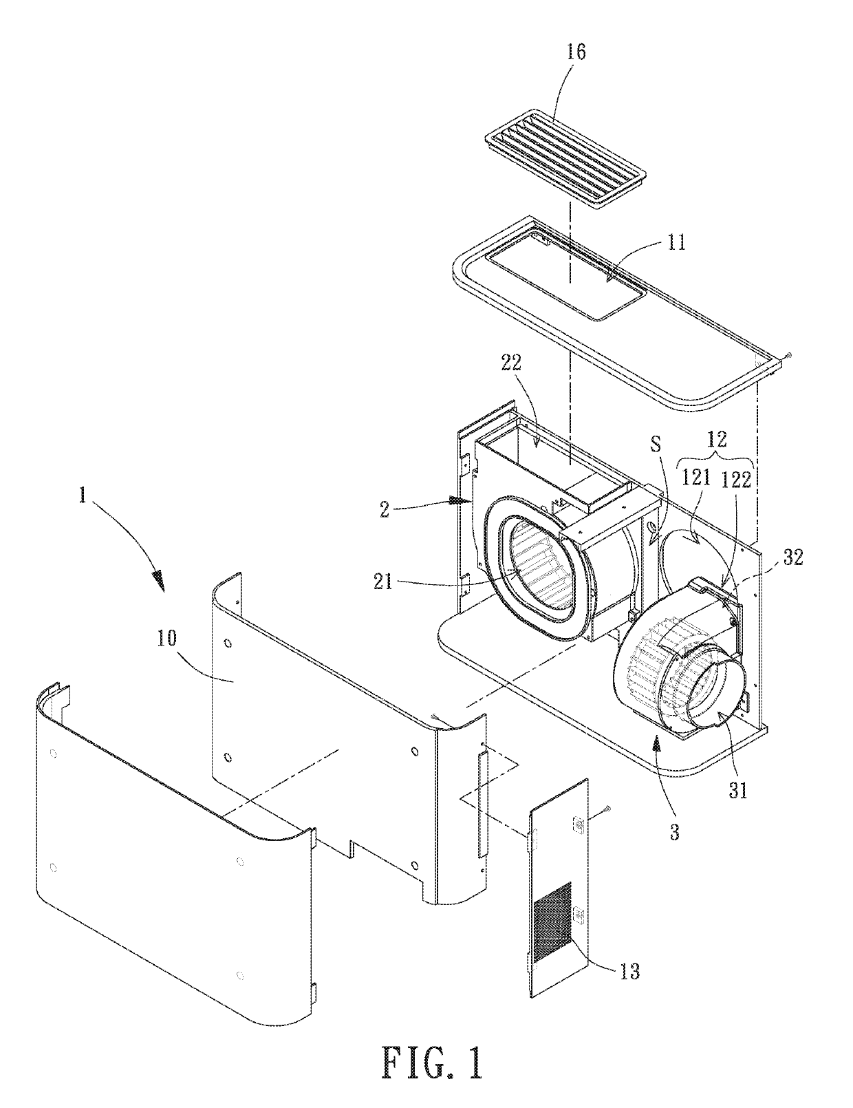
[0043]FIG. 1 shows an air exchanging device according to a first embodiment of the invention. The air exchanging device is mounted to a wall. An inner side of the wall is the indoor space, and an outer side of the wall is the outdoor space. The wall has an installation hole. The air exchanging device includes a housing 1, a first fan unit 2 and a second fan unit 3. The housing 1 has a compartment S. The first fan unit 2 and the second fan unit 3 are disposed in the compartment S.

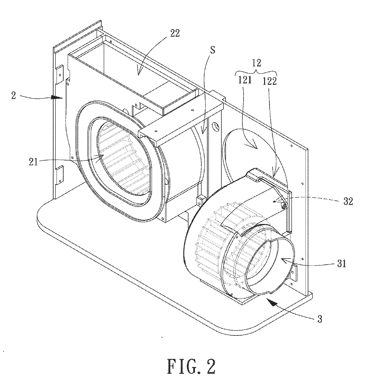
[0044]Referring to FIGS. 1 and 2, the housing 1 includes a first through-hole 11, a second through-hole 12 and a third through-hole 13. The first through-hole 11, the second through-hole 12 and the third through-hole 13 are formed on different faces of the housing 1. The first through-hole 11 and the third through-hole 13 intercommunicate with the indoor space. The second through-hole 12 intercommunicates with the outdoor space. The housing 1 includes a grid plate 16 disposed at the first through-hole 11.

[00...


PUM

PropertyMeasurementUnit
Adhesion strengthaaaaaaaaaa

Abstract

An air exchanging device according to the invention is mounted to a wall. An inner side of the wall is the indoor space, and an outer side of the wall is the outdoor space. The wall has an installation hole. The air exchanging device includes a housing, a first fan unit and a second fan unit. The housing has a compartment. The housing has a first through-hole, a second through-hole and a third through-hole. The first fan unit is received in the compartment and includes a first air inlet intercommunicating with the second through-hole, and a first air outlet intercommunicating with the first through-hole. The second fan unit is received in the compartment. The second fan unit includes a second air inlet intercommunicating with the third through-hole, and a second air outlet intercommunicating with the second through-hole.

Description

CROSS REFERENCE TO RELATED APPLICATION[0001]The application claims the benefit of Taiwan application serial No. 106137802, filed on Nov. 1, 2017, and the entire contents of which are incorporated herein by reference.BACKGROUND OF THE INVENTION1. Field of the Invention[0002]The present invention generally relates to an air exchanging device and, more particularly, to an air exchanging device which circulates the air between the indoor and outdoor spaces.2. Description of the Related Art[0003]A conventional air exchanging device is generally mounted to a wall of the building. An inner side of the wall is the indoor space, and an outer side of the wall is the outdoor space. The wall needs to form an air inlet and an air outlet. A fan is mounted to each of the inlet and the air outlet. During the operation of the fans, the external air can be guided into the indoor space via the air inlet, and the internal air can be guided to the outdoor space. Accordingly, the ventilation effect is at...

Claims


Application Information

Patent Timeline
IPC IPC(8): F24F7/013F24F3/16F24F7/003F24F8/108
CPCF24F7/013F24F3/1603B01D46/2411F24F1/0071F24F13/28B01D46/0005F24F13/32F24F7/06F24F12/006B01D46/10Y02B30/56F24F2007/0025B01D46/62F24F8/108F24F7/003
Inventor HORNG, ALEXHU, WAN-LINGLYU, LI-YANG
Owner SUNONWEALTH ELECTRIC MACHINE IND
Why Eureka
Try Eureka