Image reading apparatus and image reading system
a technology of image reading apparatus and output tray, which is applied in the field of image reading apparatus, can solve the problems of document stowage efficiency change, document stowage on the output tray may not be properly stacked, and the shape of the document transport path largely affects the size of the installation space of the apparatus and the transportability of documents
- Summary
- Abstract
- Description
- Claims
- Application Information
AI Technical Summary
Benefits of technology
Problems solved by technology
Method used
Image
Examples
first embodiment
Modifications of First Embodiment
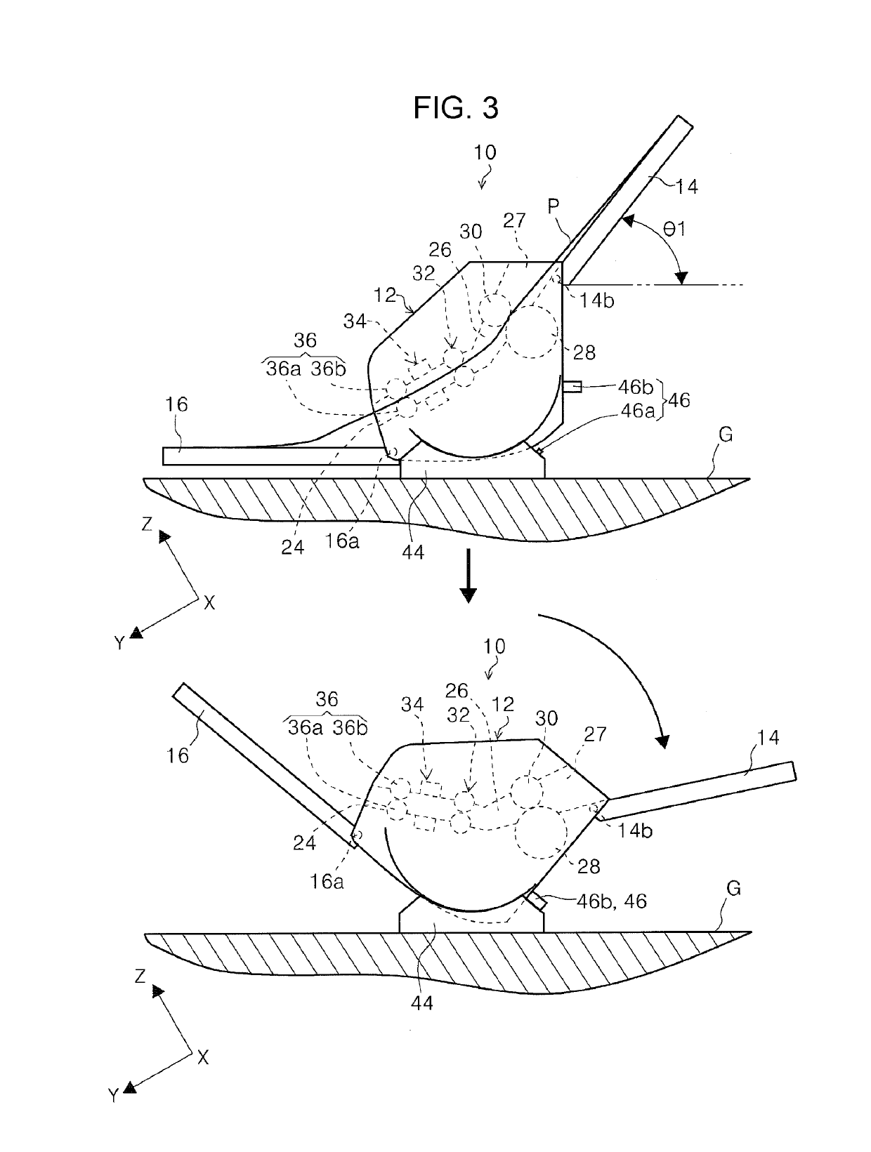
[0128](1) In this embodiment, the body posture detector 46 detects that the apparatus body 12 is in the second posture if the switch 46a is pressed. However, instead of this configuration, the body posture detector 46 may detect that the apparatus body 12 is in the first posture if the switch 46a and the pressing portion 46b are separated from each other.
[0129](2) In this embodiment, the body posture detector 46 is the switch 46a that is switched between ON and OFF with the switching of the posture of the apparatus body 12. However, instead of this configuration, for example, the body posture detector 46 may be a detector, such as an acceleration sensor, a tilt sensor, or a gyro sensor that can detect the switching of the posture of the apparatus body 12.
[0130](3) In this embodiment, when a long medium is fed, it is desirable to feed the long medium by switching the feed tray 14 to the third posture. Since the long medium has a larger weight than tha...
second embodiment
[0131]The above-described output-direction switching portion 48 included in the scanner 10 may be replaced with an output-direction switching portion 64 according to a second embodiment which is described below. The configuration of the output-direction switching portion 64 according to the second embodiment is described below with reference to FIG. 8. The same reference sign is applied to a configuration similar to that in the first embodiment.
[0132]The output-direction switching portion 64 includes, for example, a cam member 66 and a link member 68. In this embodiment, the cam member 66 is attached to the rotating shaft 16a of the output tray 16. The link member 68 is provided with an engagement portion 68a. The engagement portion 68a has a guide surface 68b on the side facing the output roller pair 36. The guide surface 68b is tilted to the −Z side. In this embodiment, the link member 68 is arranged on the +Y side of the output roller pair 36 in the medium feed direction. A lower...
third embodiment
Modification of Third Embodiment
[0149]In this embodiment, the gear train 82 performs the power transmission from the first leg portion 74 to the output tray 16. However, instead of this configuration, another power transmission portion, such as an endless belt or a chain, may perform the power transmission. Similarly, instead of the gear train 84, another power transmission portion may perform the power transmission from the second leg portion 76 to the feed tray 14.
PUM
 Abstract
Description
Claims
Application Information
 - R&D
- Intellectual Property
- Life Sciences
- Materials
- Tech Scout
- Unparalleled Data Quality
- Higher Quality Content
- 60% Fewer Hallucinations
Browse by: Latest US Patents, China's latest patents, Technical Efficacy Thesaurus, Application Domain, Technology Topic, Popular Technical Reports.
© 2025 PatSnap. All rights reserved.Legal|Privacy policy|Modern Slavery Act Transparency Statement|Sitemap|About US| Contact US: help@patsnap.com


