Boat lift

a technology for lifting boats and boats, applied in the field of boat lifts, can solve the problems of corroding metal parts, depreciation of other parts of boats, fouling of hulls, propellers, etc., and achieve the effect of improving the service life of the boat, improving the service life and improving the service li

Active Publication Date: 2019-05-09
SEA POWER BOAT ELEVATORS LLC
View PDF4 Cites 7 Cited by
  • Summary
  • Abstract
  • Description
  • Claims
  • Application Information

AI Technical Summary

Benefits of technology

The patent text describes how a boat lift can be created using a truck that has a flotation tank and pumps. The flotation tank can be attached to the boat lift and the pumps can evacuate water from the tank to create flotation. The invention allows for wider boat lifts to be transported and assembled on site easily.

Problems solved by technology

Particularly in salt water environments, water can lead to rapid corrosion of metal parts, and depreciation of other parts of the boat.
Further, in many salt water environments, storage of the boat hull in the water leads to fouling of the hull, propellers and through hulls that communicate with boat utilities.
Barnacle growth, for example, occurs in many salt water environments, and such fouling reduces performance of the boat hull and propulsion systems.
Many boats and ships are very large.

Method used


Image

  • Boat lift
  • Boat lift
  • Boat lift

Examples


Embodiment Construction

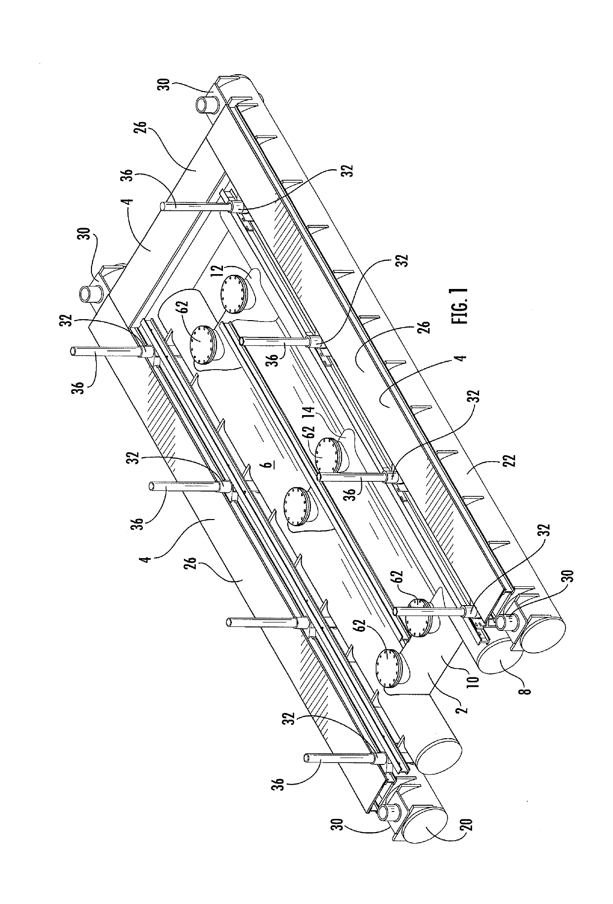
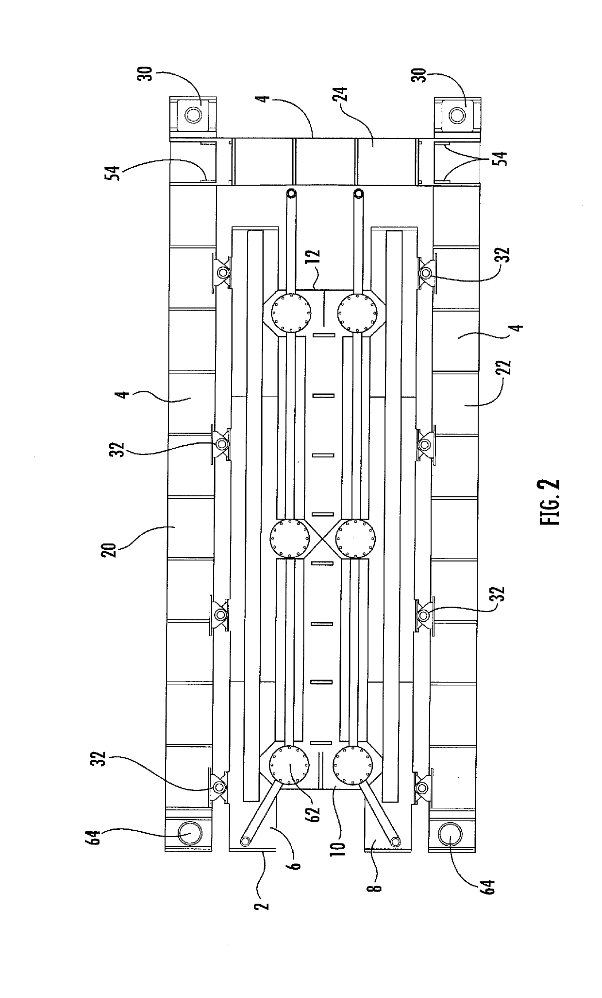
[0024]FIG. 1 and FIG. 2 show a preferred embodiment of a boat lift 2 surrounded by a catwalk 4. In this embodiment, the boat lift is characterized by two generally parallel flotation tanks 6,8 that are connected by transverse tanks 10,12 positioned near each end of the longitudinal flotation tanks and may be intermediately positioned 14.

[0025]In this embodiment, the boat lift 2 is disposed within a catwalk 4. The catwalk as shown in FIG. 1 and FIG. 2 has generally parallel flotation tanks 20,22 joined at one end by a transverse tank 24. The catwalk is open at one end to permit ingress and egress of a boat from the boat lift.

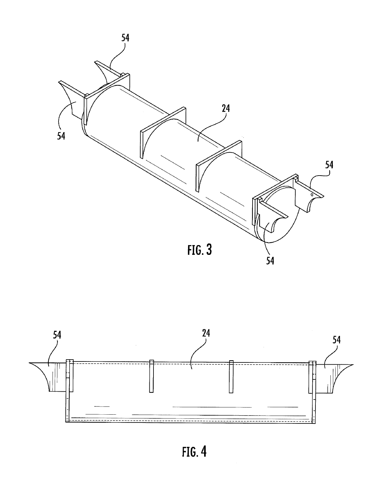
[0026]FIG. 3 and FIG. 4 show an embodiment of a transverse member 24 for joining the parallel flotation tanks 20, 22 of the catwalk. This transverse member may be formed to a desired length, which is determined based upon the desired width of the boat lift and catwalk. The flanges 54 on the ends of the transverse member or tank may be inserted into slots formed i...


PUM


Abstract

A boat lift has a transverse flotation tank that joins a first flotation tank construct and a second flotation tank construct. The transverse flotation tank has one or more pumps that evacuate water from the first flotation tank construct, the second flotation tank construct and the transverse flotation tank and create flotation of the boat lift. Modular boat lifts may be constructed according to the invention that have substantial size but are transportable by truck for construction on site.

Description

[0001]This Application is a continuation in part of U.S. application Ser. No. 16 / 143,737, filed Sep. 27, 2018, which is a continuation of U.S. application Ser. No. 15 / 467,399 filed Mar. 23, 2017, U.S. Pat. No. 10,086,919, which is a continuation in part of U.S. application Ser. No. 15 / 160,372 filed May 20, 2016, U.S. Pat. No. 9,604,709.BACKGROUND OF THE INVENTION[0002]It is desirable to store boats out of the water when not in use. Particularly in salt water environments, water can lead to rapid corrosion of metal parts, and depreciation of other parts of the boat. Further, in many salt water environments, storage of the boat hull in the water leads to fouling of the hull, propellers and through hulls that communicate with boat utilities. Barnacle growth, for example, occurs in many salt water environments, and such fouling reduces performance of the boat hull and propulsion systems.[0003]It is also desirable to lift boats out of the water for maintenance.[0004]Many boats and ships ...

Claims


Application Information

Patent Timeline
Patent Type & Authority Applications(United States)
IPC IPC(8): B63C1/06B63C1/02
CPCB63C1/06B63C1/02B63C3/06
Inventor BARNES, SEAN A.KIRBY, MICHAEL W.
Owner SEA POWER BOAT ELEVATORS LLC
Why Eureka
Try Eureka