
Event-driven safety notification based on automated incident monitoring

a technology of incident monitoring and event notification, applied in the field of event response, can solve the problems of inability to unlock, dial, beg, and the real emergency faced by many people, especially people field-deployed to dangerous situations, and achieve the effect of facilitating automated respons

Active Publication Date: 2019-05-09
ALERT MEDIA
View PDF8 Cites 2 Cited by
  • Summary
  • Abstract
  • Description
  • Claims
  • Application Information

AI Technical Summary

Benefits of technology

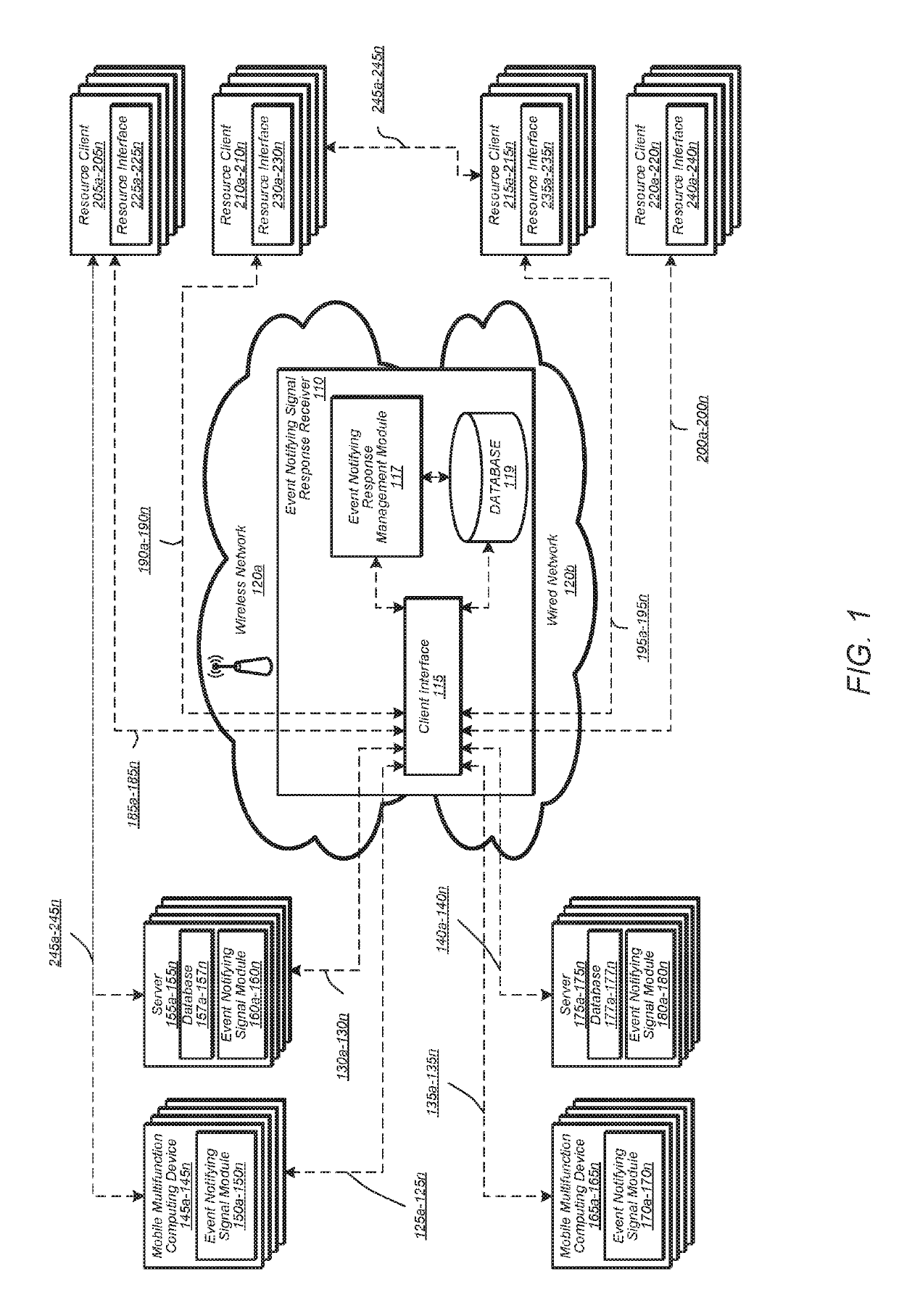
The patent describes a system for automated response to event notifying signals. The system includes a network monitoring module, assessment module, resource monitoring module, and resource response module. The network monitoring module can monitor signals from various sources like social media, news media, weather data, and so on. The assessment module can analyze the source, frequency, and transmission medium of the signals to assess the likelihood of a relevant incident. The resource monitoring module can monitor the status of the resources assigned to the incident. The system can also detect sensors associated with the resources, such as cameras, thermometers, microphones, speakers, and more. The technical effects of the system include improving efficiency in identifying relevant incidents and allowing for quicker response by resource teams.

Problems solved by technology

In emergencies in the real world, the time and capacity necessary to perform all of these operations are generally not available to persons subject to the emergency during the course of the emergency.
In the case of medical emergencies, the user may further lack capacity to “unlock, dial, and beg for help” as he or she teeters on the border of lost consciousness.
The paradigm of “unlock, dial, and beg for help” works for some people in some situations, but the real emergencies faced by many people, particularly people field-deployed to dangerous situations, are not well-served.
For example, event notifying signals predominantly transmitting from wired sources may be indicative of a wireless network failure.
Event notifying signals predominantly transmitting from wireless sources may be indicative of a power distribution failure.
Such a disparity or contradiction may indicate that one or more source or transmission medium has been jeopardized.

Method used


Image

  • Event-driven safety notification based on automated incident monitoring
  • Event-driven safety notification based on automated incident monitoring
  • Event-driven safety notification based on automated incident monitoring

Examples


Embodiment Construction

[0025]Before Reference will now be made in detail to embodiments, examples of which are illustrated in the accompanying drawings. In the following detailed description, numerous specific details are set forth in order to provide a thorough understanding of the present disclosure. However, it will be apparent to one of ordinary skill in the art that some embodiments may be practiced without these specific details. In other instances, well-known methods, procedures, components, circuits, and networks have not been described in detail so as not to unnecessarily obscure aspects of the embodiments.

[0026]It will also be understood that, although the terms first, second, etc. may be used herein to describe various elements, these elements should not be limited by these terms. These terms are only used to distinguish one element from another. For example, a first contact could be termed a second contact, and, similarly, a second contact could be termed a first contact, without departing fro...


PUM


Abstract

A system for facilitating automated response to an event notifying signal, the system including a network monitoring module, an assessment module, a resource monitoring module, and a resource response module. The network monitoring module is configured for monitoring signals received over a data network for a presence of one or more event notifying signals indicative of a relevant incident. The assessment module is configured for assessing a response of the one or more event notifying signals and a resource tasked to the response. The resource monitoring module is configured for monitoring a status of a resource tasked to the response of the event notifying signal. The resource response module is configured for communicating the response to the resource tasked to the response.

Description

CROSS REFERENCE TO RELATED APPLICATIONS[0001]This application claims priority from and is a continuation-in-part of U.S. patent application Ser. No. 15 / 796,291 filed Oct. 27, 2017, titled “Automated Response to Duress in Distress Signals” (now U.S. Pat. No. 10,176,701). This application further claims priority to U.S. Provisional Application No. 62 / 624,487 filed Jan. 31, 2018, titled “Event-Driven Safety Notification Based on Automated Incident Monitoring.” Further, as a continuation-in-part of U.S. application Ser. No. 15 / 796,291, this application claims priority to U.S. patent application Ser. No. 15 / 252,788 filed Aug. 31, 2016 (now U.S. Pat. No. 9,870,695), which claims priority from and is a continuation of U.S. patent application Ser. No. 15 / 179,207, filed Jun. 10, 2016 (now U.S. Pat. No. 9,483,931), which claims priority from and is a continuation of U.S. patent application Ser. No. 14 / 886,552 filed Oct. 19, 2015 (now U.S. Pat. No. 9,390,614), which claims benefit of priority ...

Claims


Application Information

Patent Timeline
Patent Type & Authority Applications(United States)
IPC IPC(8): G08B25/01H04W4/02H04M1/725G08B25/10H04W12/08H04W4/90H04M1/72409H04M1/72412H04M1/72421H04M1/72424
CPCG08B25/016H04W4/02H04M1/72541H04M1/72538G08B25/10H04M1/72527H04W12/08H04W4/90H04W88/02H04W4/80H04M1/72409H04M1/72412H04M1/72421H04M1/72424
Inventor CRUVER, BRIANMILLER, MATTHEW
Owner ALERT MEDIA
Learn More