
Ventilated skylight

Active Publication Date: 2019-05-16
SUNCAST TECH
View PDF8 Cites 3 Cited by
  • Summary
  • Abstract
  • Description
  • Claims
  • Application Information

AI Technical Summary

Benefits of technology

This patent describes a ventilated skylight for shed enclosures that allows air to circulate and reduces humidity. It is secured to the roof with a single flange and includes a cap member made of translucent material that allows light to illuminate the inside of the shed. The base member has slots for air circulation and the cap member prevents rain water from entering the slots. Overall, this invention provides a low-cost ventilation solution that improves the air quality and comfort of shed enclosures.

Problems solved by technology

Sheds are not designed for receipt of electrical power, so the use of powered fans, dehumidifiers, or air conditioners is not possible.
A sealed enclosure can cause numerous problems, the most noticeable being an excess amount of moisture buildup within the shed, which can accelerate rusting of metal based devices.
Lack of proper ventilation could cause premature aging of such products, especially internal combustion engines where cylinders can rust.
A problem with simply using spacing to allow ventilation is that, during rain, water can easily enter the shed through the spacing.
A clear piece of plastic can be placed in a roof of a shed, but that does not provide ventilation and may be another source for water leaks.
However, this device is difficult and expensive to manufacture, in that the central oriel is made from an expensive clear material that must be inserted into specially designed opaque mounts, which in turn are attached to the roof.

Method used


Image

  • Ventilated skylight
  • Ventilated skylight
  • Ventilated skylight

Examples


Embodiment Construction

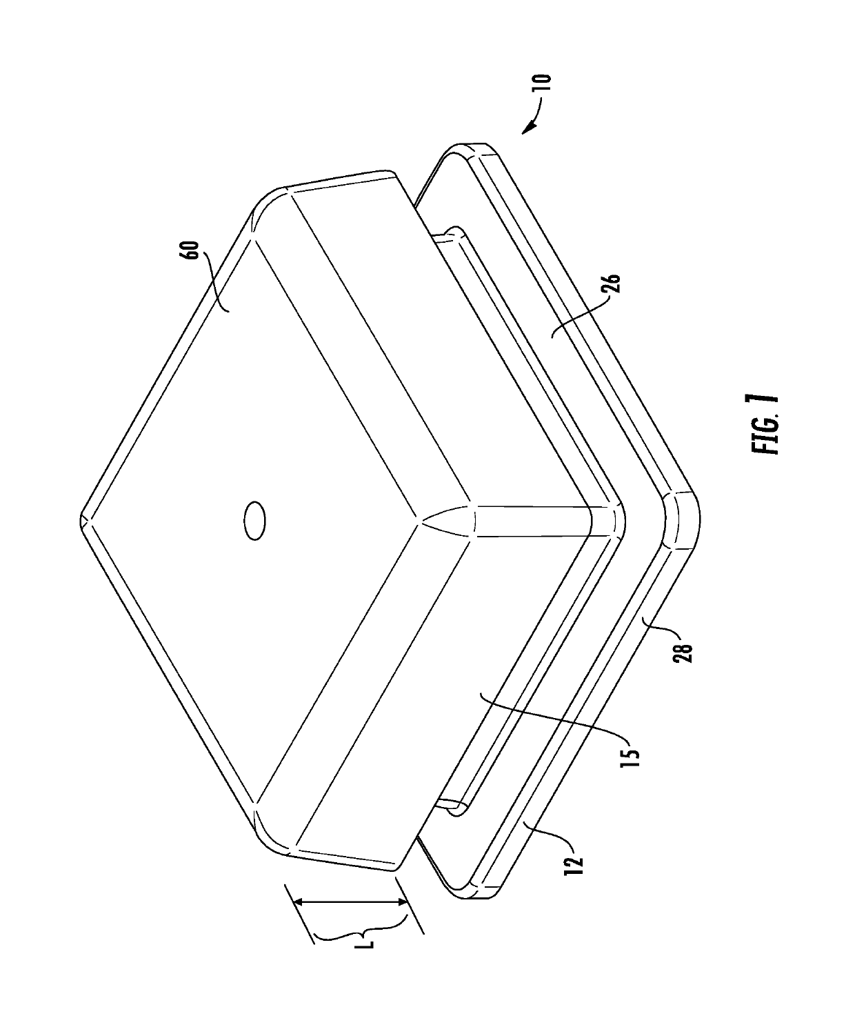
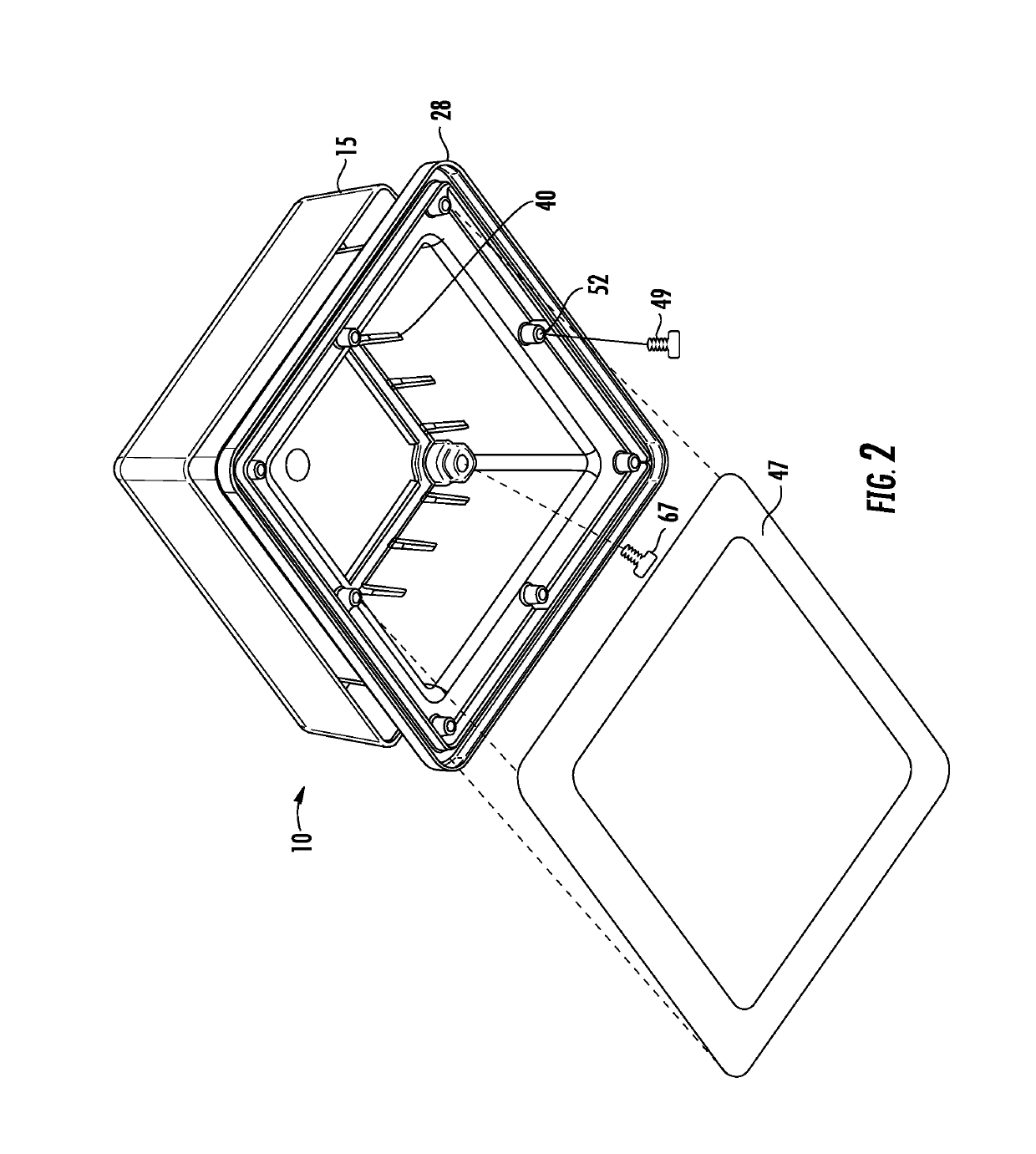
[0024]Now referring to the figures in general, set forth is a ventilated skylight 10 having a base member 12 and a cap member 15. The base member 12 is formed by four upright sidewalls and a flange. a first upright wall 14 adjoining a second upright wall 16, adjoining a third upright wall 18, which adjoins a fourth upright wall 20. The base member is formed from a single piece of injection molded plastic to form a substantially square enclosure. Upright wall 14 is further defined by a top edge 22 which is continuous around the top of the four upright walls, as well as a bottom edge 24 which terminates on the upper surface 26 of flange 28. Each of the upright walls 14, 16, 18 and 20, terminate in a corner as they adjoin the next wall. Using upright wall 14 for illustration, corner 30 is formed as the wall adjoins upright wall 16. Near the top edge 22 of corner 30, a receptacle 32 is indented from the top edge 22, providing an alignment wall 34 which surrounds a fastener aperture 36. ...


PUM


Abstract

A ventilated skylight for a shed enclosure. The ventilated skylight formed from a base member securable to the roof of a residential shed. The base member has a flange for receipt of a gasket for securement directly to the shed roof. Upright walls of the base member include a plurality of slots constructed and arranged to allow air to circulate through the shed. A cap member is securable to the base member with side walls to prevent rain water from entering the vertical slots. In a preferred embodiment, the cap member is made of a translucent material to allow light to illuminate the inside of the shed enclosure.

Description

FIELD OF THE INVENTION[0001]This invention relates to the field of venting devices, and in particular, to a passive ventilated skylight for a shed enclosure.BACKGROUND OF THE INVENTION[0002]Ventilation is necessary for most any enclosed structure. Enclosed structures known as residential sheds have a particular need for venting, as they are designed for outdoor placement and, thus, subjected to the elements throughout the year. A residential shed used for storage may not be opened for weeks or even months. Sheds are not designed for receipt of electrical power, so the use of powered fans, dehumidifiers, or air conditioners is not possible.[0003]A sealed enclosure can cause numerous problems, the most noticeable being an excess amount of moisture buildup within the shed, which can accelerate rusting of metal based devices. For instance, a shed can be used to store lawnmowers tractors, bicycles, and so forth. Lack of proper ventilation could cause premature aging of such products, esp...

Claims


Application Information

Patent Timeline
IPC IPC(8): E04D13/03
CPCE04D13/0325F24F7/02F24F2221/20E04D13/0305
Inventor REYBURN, JUSTIN CHARLESVOGLER, MICHAEL R.
Owner SUNCAST TECH
Learn More