Check patentability & draft patents in minutes with Patsnap Eureka AI!

Floor mat structure and floor mat assembly

a technology of floor mats and floor mats, applied in the field of floor mat structures and floor mat assemblies, can solve the problems of not being economically effective, and achieve the effect of reducing the probability of damage to the floor mat structur

Active Publication Date: 2019-05-23
COMPAL ELECTRONICS INC
View PDF0 Cites 1 Cited by
  • Summary
  • Abstract
  • Description
  • Claims
  • Application Information

AI Technical Summary

Benefits of technology

The disclosed floor mat structure includes a lower cover and an upper cover with a plurality of fasteners. Each fastener includes a sleeve and a screw, which is used to secure the lower cover to the upper cover. The technical effect of this floor mat structure is improved stability and durability.

Problems solved by technology

However, the known floor mat only has a function of providing buffer force and cannot satisfy users' needs for multi-functions of a product; thus, the known floor mat is not economic effective.

Method used


Image

  • Floor mat structure and floor mat assembly
  • Floor mat structure and floor mat assembly
  • Floor mat structure and floor mat assembly

Examples


Embodiment Construction

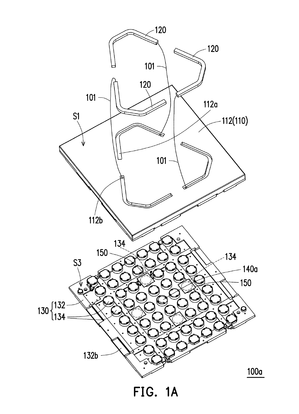
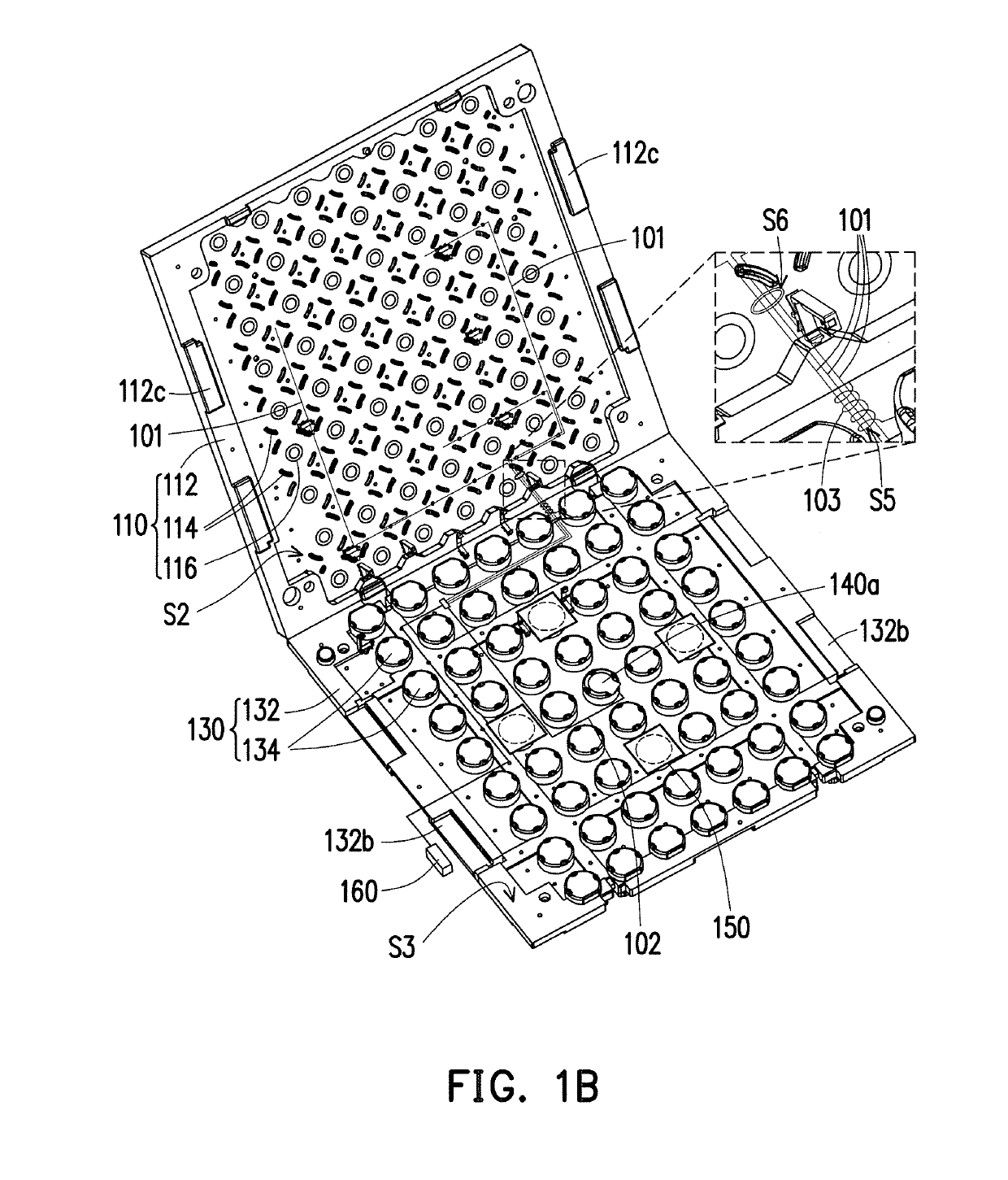
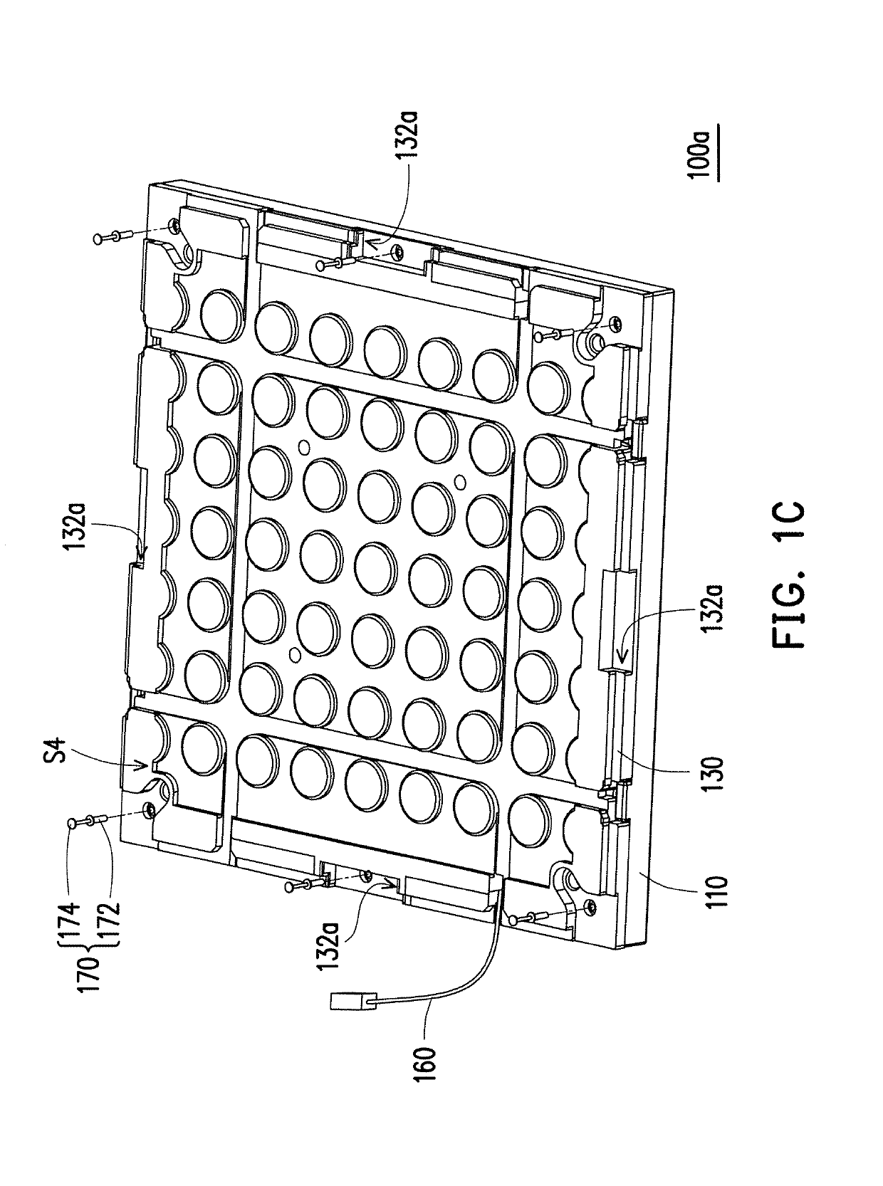
[0046]FIG. 1A is a partial exploded schematic view of a perspective of a floor mat structure of an embodiment of the disclosure. FIG. 1B is a schematic view of the floor mat structure of FIG. 1A with its upper cover opened with respect to its lower cover. FIG. 1C is a partial exploded schematic view of another perspective of the floor mat structure of FIG. 1 A. FIG. 1D is a schematic view of a floor mat structure of another embodiment of the disclosure.

[0047]Please refer to FIG. 1A, FIG. 1B and FIG. 1C simultaneously. A floor mat structure 100a of the present embodiment includes an upper cover 110, a plurality of light bars 120 (three light bars are shown schematically in FIG. 1A), a lower cover 130 and at least one sensing element 140a (one sensing element is shown schematically in FIG. 1A). The upper cover 110 includes a main body 112 and a plurality of indicator blocks 114. The main body 112 has an upper surface Si and a lower surface S2 that are opposite to each other. The indic...


PUM


Abstract

A floor mat structure includes an upper cover, a plurality of light bars, a lower cover and at least one sensing element. The upper cover includes a main body and a plurality of indicator blocks. The main body has an upper surface and a lower surface opposite to each other. The indicator blocks are separated from one another and are disposed on the lower surface. The light bars are disposed on the upper cover and are embedded in the upper surface. The lower cover assembled to the upper cover includes a base and a plurality of bumps. The base has a configuration surface facing the lower surface. The bumps are separated from one another and are disposed on the configuration surface, wherein orthographic projections of the indicator blocks on the configuration surface does not overlap the bumps. The sensing element is disposed on the lower cover and are located at at least one bump. When the sensing element senses pressure from the upper cover, the light bars illuminate. Also, a floor mat assembly is provided.

Description

CROSS-REFERENCE TO RELATED APPLICATION[0001]This application claims the priority benefit of U.S. provisional application Ser. No. 62 / 588,906, filed on Nov. 20, 2017. The entirety of the above-mentioned patent application is hereby incorporated by reference herein and made a part of this specification.BACKGROUNDTechnical Field[0002]The disclosure relates to a floor mat structure and a floor mat assembly, and particularly to a floor mat structure having a sensing function and a floor mat assembly.Description of Related Art[0003]General floor mats are mostly made of elastic materials, and a larger cushion may be formed through splicing the edges of the floor mats to provide buffer force to protect users so that the users may play and exercise on the cushion. However, the known floor mat only has a function of providing buffer force and cannot satisfy users' needs for multi-functions of a product; thus, the known floor mat is not economic effective.SUMMARY[0004]The disclosure provides a...

Claims


Application Information

Patent Timeline
Patent Type & Authority Applications(United States)
IPC IPC(8): A63B6/00F21V33/00H05B37/02
CPCA63B6/00F21V33/008H05B37/0227A47G27/0243F21V33/00A61B2562/046A61B5/1126A61B2562/0247A61B2562/0252A61B2560/0443H05B47/115Y02B20/40A61B5/11
Inventor YEN, SHIH-HSIUNGOU, CHIA-HUNGHUANG, TA-HSIANGLAI, JUNE-PENGTSENG, FU-HSUANCHANG, CHING-TAI
Owner COMPAL ELECTRONICS INC
Features
  • R&D
  • Intellectual Property
  • Life Sciences
  • Materials
  • Tech Scout
  • Unparalleled Data Quality
  • Higher Quality Content
  • 60% Fewer Hallucinations
Learn More