Tire pressure positioning method and apparatus

a positioning method and tire pressure technology, applied in the direction of tire measurement, vehicle components, transportation and packaging, etc., can solve the problems the monitoring apparatus and program processing is relatively complex, and the problem of how to simplify the automatic positioning method of tire pressure sensors becomes the problem, etc., to simplify the data collection and calculation process, improve system operation efficiency, and reduce the amount of data processing

Active Publication Date: 2019-05-23
AUTEL INTELLIGENT TECHNOLOGY CORP LTD
View PDF0 Cites 0 Cited by
  • Summary
  • Abstract
  • Description
  • Claims
  • Application Information

AI Technical Summary

Benefits of technology

[0011]According to the tire pressure positioning method and apparatus that are provided in the embodiments of the present application, turning information used to indicate turning of a vehicle and a y-axis acceleration of a tire pressure sensor in a tire of the vehicle are obtained, to determine the y-axis acceleration of the tire pressure sensor under the turning information. A position of the tire pressure sensor is determined according to the turning information and the y-axis acceleration of the tire pressure sensor. For example, the tire pressure sensor is at a left-front position, a left-rear position, a right-front position or a right-rear position in the vehicle. In the embodiments of the present application, information about the y-axis acceleration of the tire pressure sensor is processed. Compared with a method in the prior art in which information about an x-axis acceleration and information about a z-axis acceleration need to be processed simultaneously, the method can reduce a data processing amount, thereby simplifying data collection and calculation processes and improving system operation efficiency.

Problems solved by technology

Consequently, a monitoring apparatus and program processing are relatively complex.
Therefore, how to simplify the tire pressure sensor automatic positioning method becomes the problem that urgently needs to be resolved today.
A technical problem to be resolved in the present application is that in a tire pressure sensor automatic positioning method in the prior art, a monitoring apparatus and program processing are relatively complex due to simultaneous detection on an x-axis acceleration and a z-axis acceleration.

Method used


Image

  • Tire pressure positioning method and apparatus
  • Tire pressure positioning method and apparatus
  • Tire pressure positioning method and apparatus

Examples


embodiment 1

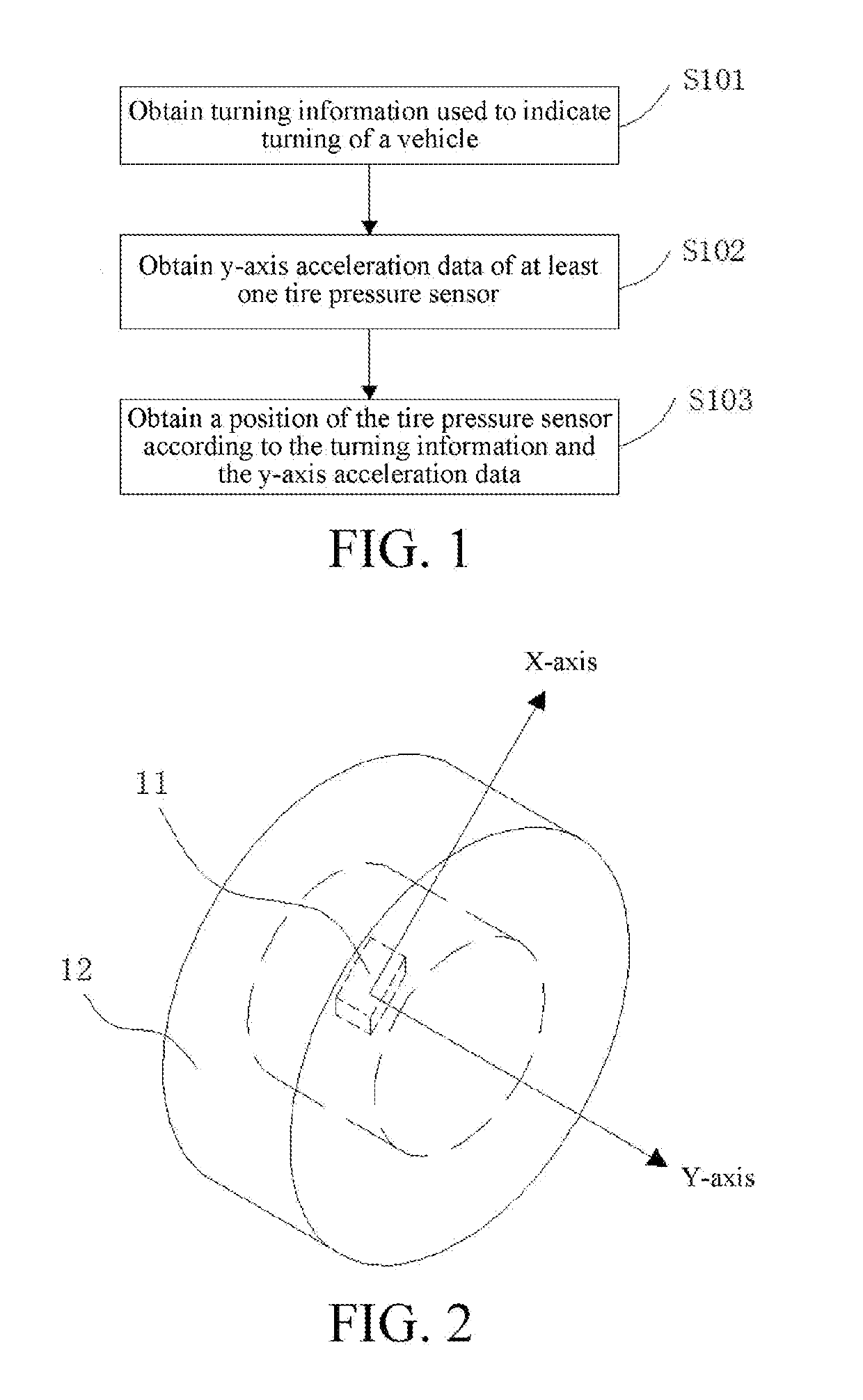
[0027]An implementation of a tire pressure sensor positioning method is shown in FIG. 1 to FIG. 4, including the following steps:

[0028]S101: Obtain turning information used to indicate turning of a vehicle.

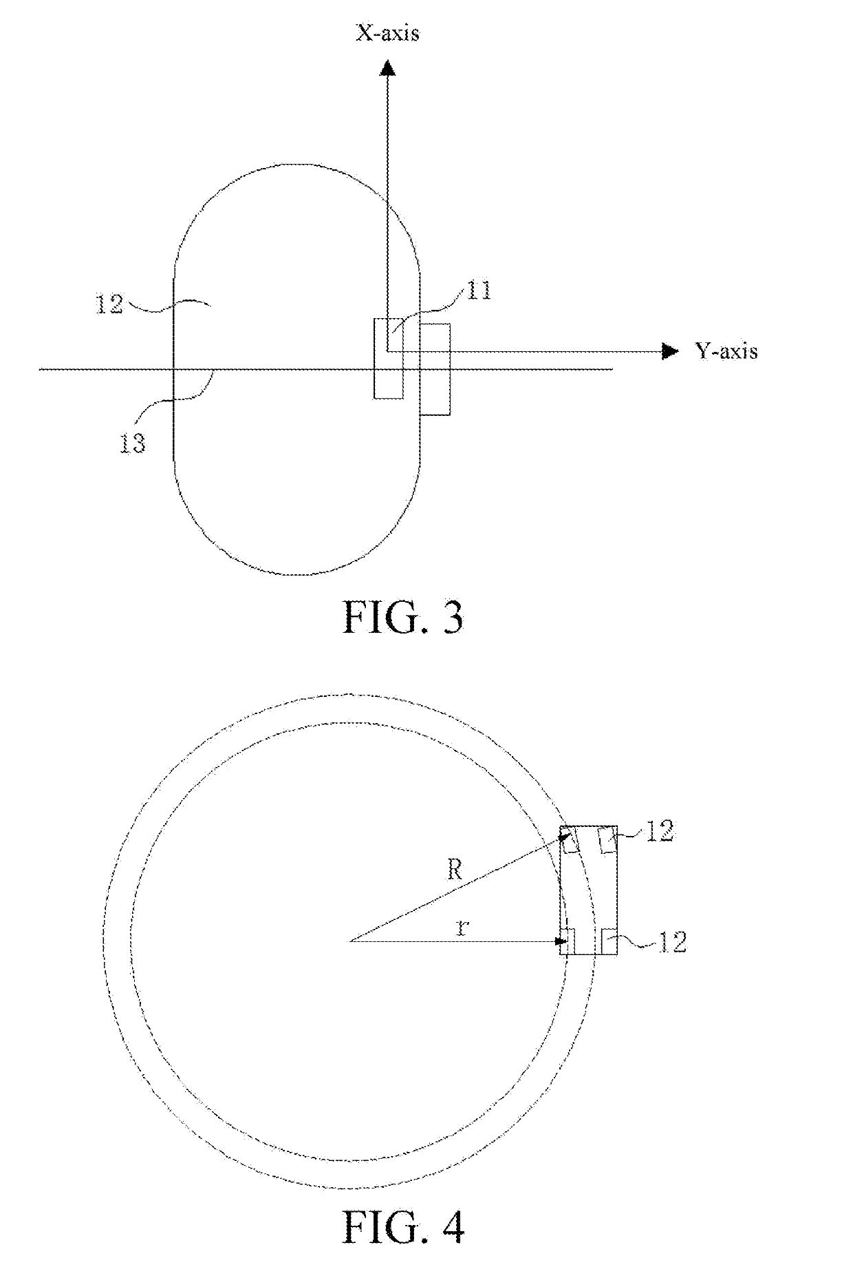
[0029]S102: Obtain a y-axis acceleration of a tire pressure sensor 11 in a tire 12 of the vehicle, where a y-axis is an axial direction parallel to a wheel bearing 13, as shown in FIG. 2 and FIG. 3.

[0030]S103: Determine a position of the tire pressure sensor 11 according to the turning information and the y-axis acceleration.

[0031]According to the tire pressure positioning method, turning information used to indicate turning of a vehicle and a y-axis acceleration of a tire pressure sensor 11 in a tire 12 of the vehicle are obtained, to determine the y-axis acceleration of the tire pressure sensor 11 under the turning information. A position of the tire pressure sensor 11 is determined according to the turning information and the y-axis acceleration of the tire pressure sensor 11. ...

embodiment 2

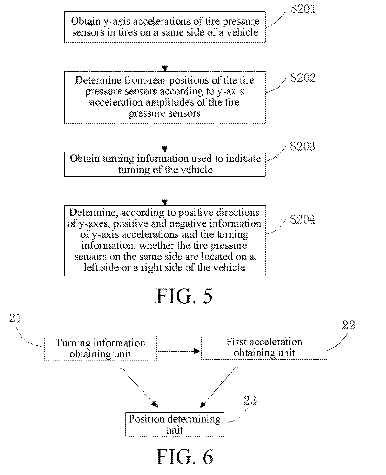
[0043]Another implementation of a tire pressure sensor positioning method is shown in FIG. 5, including the following steps:

[0044]S201: Obtain y-axis accelerations of tire pressure sensors 11 in tires 12 located on a same side of a vehicle, where there are at least two tire pressure sensors 11.

[0045]S202: Determine front-rear positions of the tire pressure sensors 11 according to y-axis acceleration amplitudes of the tire pressure sensors 11, where a tire pressure sensor 11 having a larger y-axis acceleration amplitude is located in front of a tire pressure sensor 11 having a smaller y-axis acceleration amplitude.

[0046]According to the foregoing tire pressure sensor positioning method, y-axis accelerations of tire pressure sensors 11 in tires 12 located on a same side of a vehicle are obtained, where there are at least two tire pressure sensors 11. Further, front-rear positions of the tire pressure sensors 11 all on a left side or a right side may be determined according to y-axis a...

embodiment 3

[0051]An implementation of a tire pressure sensor positioning apparatus is shown in FIG. 6, including: a turning information obtaining unit 21, a first acceleration obtaining unit 22 and a position determining unit 23. The turning information obtaining unit 21 is configured to obtain turning information used to indicate turning of a vehicle. The first acceleration obtaining unit 22 is configured to obtain a y-axis acceleration of a tire pressure sensor 11 in a tire 12 of the vehicle, where a y-axis is an axial direction parallel to a wheel bearing 13, as shown in FIG. 3. The position determining unit 23 is configured to determine a position of the tire pressure sensor 11 according to the turning information and the y-axis acceleration.

[0052]According to the tire pressure positioning apparatus, the turning information obtaining unit 21 obtains the turning information used to turning of the vehicle, and the first acceleration obtaining unit 22 obtains the y-axis acceleration of the ti...


PUM


Abstract

The present application provides a tire pressure positioning method and apparatus. The method includes: obtaining turning information used to indicate turning of a vehicle; obtaining a y-axis acceleration of a tire pressure sensor in a tire of the vehicle, where a y-axis is an axial direction parallel to a wheel bearing; and determining a position of the tire pressure sensor according to the turning information and the y-axis acceleration. Information about the y-axis acceleration of the tire pressure sensor is processed. Compared with a method in the prior art in which information about an x-axis acceleration and information about a z-axis acceleration need to be processed simultaneously, the method can reduce a data processing amount, thereby simplifying data collection and calculation processes and improving system operation efficiency.

Description

BACKGROUNDTechnical Field[0001]The present application relates to the field of automobile accessory technologies, and in particular, to a tire pressure positioning method and apparatus.Related Art[0002]A tire pressure monitoring system (TPMS) is a vehicle active safety system that adopts a radio transmission technology, collects data such as a vehicle tire acceleration, pressure and a temperature by using a highly sensitive micro wireless tire pressure sensor fixed inside a vehicle tire in a moving state or a static state, sends the data to a host in a cab, displays the related data such as the vehicle tire pressure and the temperature in a digital form in real time and warns a driver in manners such as buzzing and audio when a tire is abnormal.[0003]Generally, there are four existing tire pressure sensors, which are respectively installed on four wheels of a vehicle. Receiving antennas for performing wireless data transmission with the tire pressure sensors are installed at a front...

Claims


Application Information

Patent Timeline
Patent Type & Authority Applications(United States)
IPC IPC(8): B60C23/04
CPCB60C23/0489B60C23/0488B60C23/0416B60C23/04
Inventor WU, YONGLEI, FUSHENG
Owner AUTEL INTELLIGENT TECHNOLOGY CORP LTD
Why Eureka
Try Eureka