Flow-through pulsing assembly for use in downhole operations

Active Publication Date: 2019-05-23
IMPULSE DOWNHOLE SOLUTIONS LTD
View PDF12 Cites 17 Cited by
  • Summary
  • Abstract
  • Description
  • Claims
  • Application Information

AI Technical Summary

Problems solved by technology

Stalling and slip-stick issues can result in damage to drilling string components.
Further, when drilling deep bore holes in the earth, sections of the bore hole can cause drag or excess friction which may hinder proper weight transfer to the drill bit or causes erratic torque in the drill string.
These effects may have the result of slowing down the rate of penetration, creating bore hole deviation issues, o

Method used


Image

  • Flow-through pulsing assembly for use in downhole operations
  • Flow-through pulsing assembly for use in downhole operations
  • Flow-through pulsing assembly for use in downhole operations

Examples


Embodiment Construction

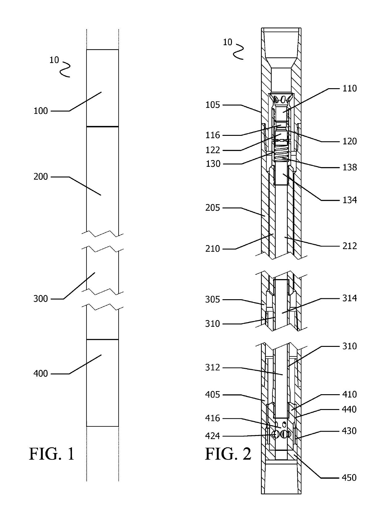
[0028]As is generally understood by those skilled in the art, in prior art downhole assemblies employing a power section (motor), drilling fluid passes from a bore or passage above the motor and into the motor to thereby activate the motor. This may be achieved by causing a rotor to rotate, and consequently drive any downhole tools linked to the rotor, such as a friction tool. Fluid passing through the motor enters the bore or passage downstream of the rotor. As can be seen in the particular example assembly 10 illustrated in FIGS. 1 and 2 and as discussed in further detail below, the drilling fluid passes from the motor section 200 to the drive section 300 and on to the valve section 400; the rotor 210 is mechanically linked to the valve assembly in the valve section 400 to thereby drive a rotating component of the valve assembly.

[0029]The rotation speed and horsepower of the motor is determined in part by the flow rate of drilling fluid through the motor. In a Moineau motor (“mud ...


PUM


Abstract

A flow-through assembly for use in a downhole drilling string includes a Moineau-type motor, means for selectively activating the motor such as a ball catch component that selectively causes drilling fluid to enter into or bypass the motor, and a rotating variable choke assembly that is driven by a rotor of the motor. The choke assembly varies the flow rate of drilling fluid as rotation causes ports of the choke assembly to enter into and out of alignment with each other. In one embodiment, the choke assembly comprises a faceted rotary component including bypass ports on the facets of the component. In another embodiment, the choke assembly comprises a tapered rotary component that rotates in a complementarily tapered stationary component.

Description

CROSS-REFERENCE TO RELATED APPLICATIONS[0001]This application is a continuation of International Application No. PCT / CA2017 / 050828, filed Jul. 7, 2017, which claims priority to U.S. Provisional Application No. 62 / 359,683, filed Jul. 7, 2016, the entireties of which are incorporated herein by reference.TECHNICAL FIELD[0002]The present disclosure relates to downhole drilling assemblies for use in horizontal and vertical drilling operations, and in particular valve control within a drilling string.TECHNICAL BACKGROUND[0003]In oil and gas production and exploration, downhole drilling can be accomplished with a downhole drill powered by a mud motor. The drilling fluid used to drive the motor also assists the drilling process in other ways, for example by dislodging and removing drill cuttings, cooling the drill bit, and providing pressure to prevent formation fluids from entering the wellbore.[0004]Stalling and slip-stick issues can result in damage to drilling string components. It is b...

Claims


Application Information

Patent Timeline
IPC IPC(8): E21B34/14E21B4/02F03C2/08F04C2/107F04C13/00F04C14/24
CPCE21B34/14E21B4/02F03C2/08F04C2/107F04C13/008F04C14/24E21B28/00E21B31/005E21B47/18E21B34/06E21B34/142
Inventor LORENSON, TROYLEROUX, KEVINPARENTEAU, DWAYNEKINSELLA, DOUG
Owner IMPULSE DOWNHOLE SOLUTIONS LTD
Why Eureka
Try Eureka