Connector plug for connecting an ignition coil to a spark plug

Active Publication Date: 2019-05-23
BORGWARNER BERU SYST
View PDF0 Cites 3 Cited by
  • Summary
  • Abstract
  • Description
  • Claims
  • Application Information

AI Technical Summary

Benefits of technology

[0004]This disclosure shows how a connector plug for connecting a spark plug to an ignition coil can be produced cost-effectively, which—if required—can also be mounted in a curved state on an engine with little effort, and is protected from damage by a mechanically robust protective tube.
[0005]The protective tube of an inventive connector plug has a predetermined bending point with a reduced bendin

Problems solved by technology

The production of both straight and

Method used


Image

  • Connector plug for connecting an ignition coil to a spark plug
  • Connector plug for connecting an ignition coil to a spark plug
  • Connector plug for connecting an ignition coil to a spark plug

Examples


Example

[0018]The embodiments described below are not intended to be exhaustive or to limit the invention to the precise forms disclosed in the following detailed description. Rather, the embodiments are chosen and described so that others skilled in the art may appreciate and understand the principles and practices of this disclosure.

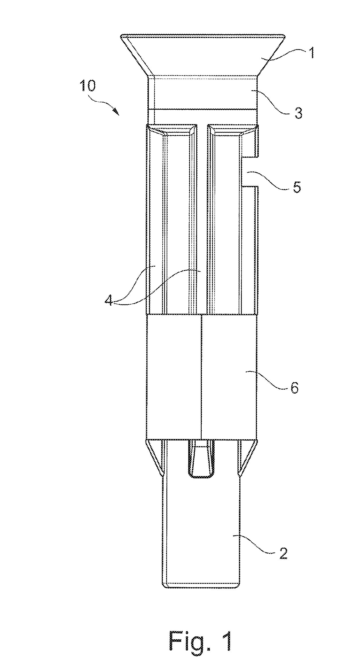
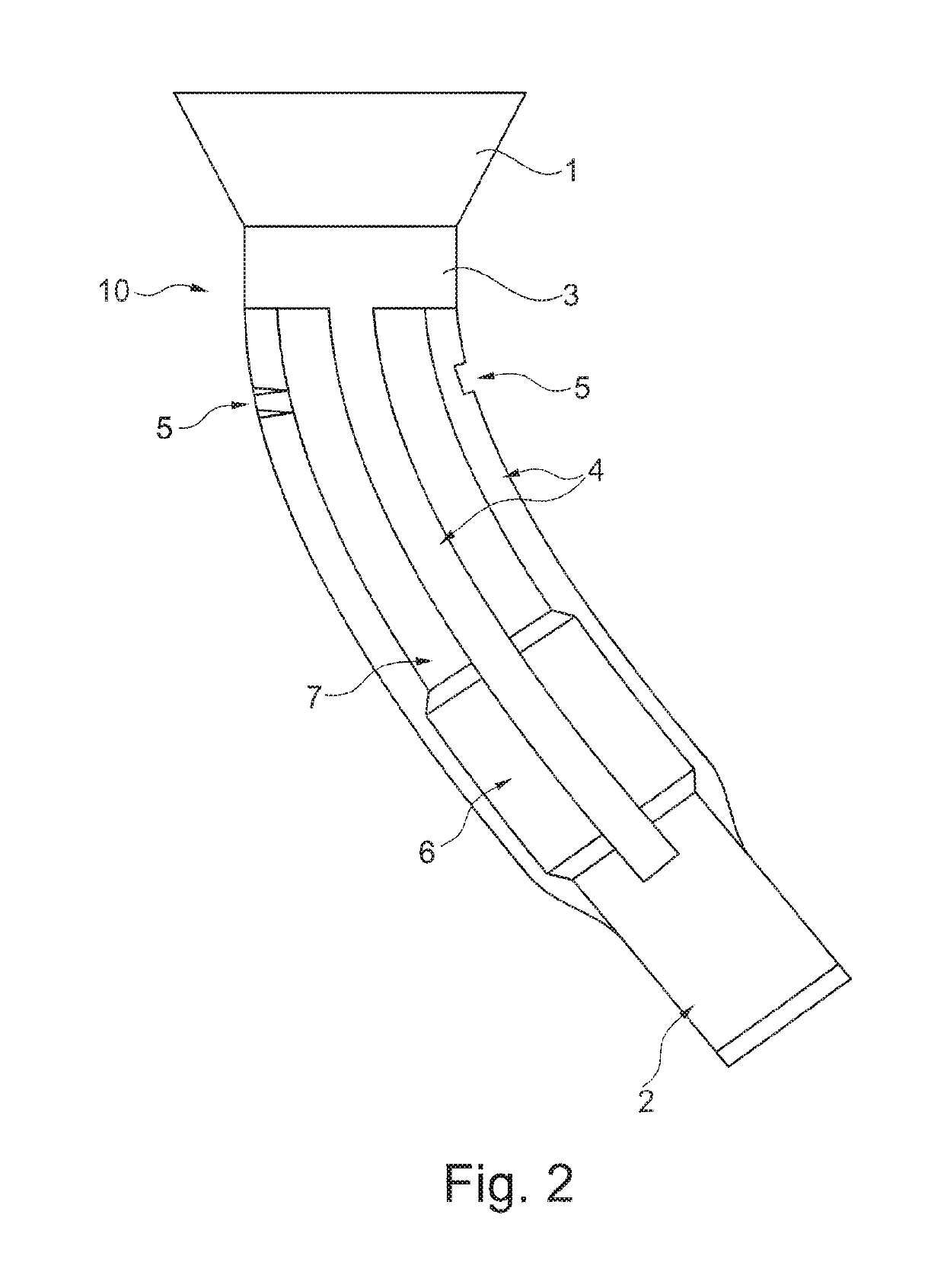
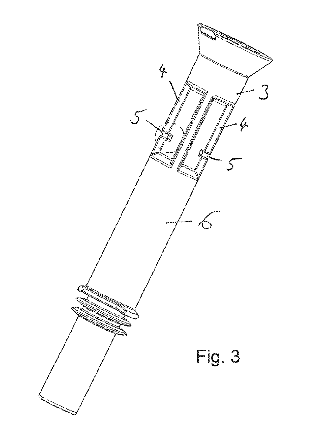
[0019]The connector plug 10 shown in FIG. 1 is used to connect an ignition coil to a spark plug of an internal combustion engine. For this purpose, the upper end 1 of the connector plug 10 in the figures is connected to the ignition coil, and the lower end 2 in the figures is connected to the spark plug. The connector plug 10 contains an electrical conductor, for example in the form of a metallic coil spring, which is surrounded by a protective tube 3, and in operation connects the high-voltage contact of an ignition coil to the terminal contact of a spark plug in an electrically conducting manner. The protective tube 3 can be seen in FIGS. 1 and 2, and may be...


PUM


Abstract

A connector plug is described for connecting an ignition coil to a spark plug, comprising an electrical conductor, which has a first end for contacting the ignition coil and a second end for contacting the spark plug, and a protective tube, which surrounds the electrical conductor. In accordance with this disclosure it is proposed that the protective tube has a predetermined bending point with a reduced bending stiffness.

Description

RELATED APPLICATIONS[0001]This application claims priority to DE 10 2017 127 174.0, filed Nov. 17, 2017, and also claims priority to DE 10 2018 108 292.4, filed Apr. 9, 2018, both of which are incorporated herein by reference in their entirety.BACKGROUND AND SUMMARY[0002]This disclosure is based on a connector plug for connecting an ignition coil to a spark plug. Connector plugs of this type are generally known from DE 10 2011 082 231 A1, JP 2011-134857 A and DE 10 2015 110 309 A1, for example.[0003]Depending on the geometric conditions on an engine, connector plugs with either a straight or a curved protective tube are required. The production of both straight and curved protective tubes is expensive. There is therefore a need for connector plugs that can be bent as required, such as the connector plug of known art from JP 2011-134857 A.[0004]This disclosure shows how a connector plug for connecting a spark plug to an ignition coil can be produced cost-effectively, which—if require...

Claims


Application Information

Patent Timeline
IPC IPC(8): H01T13/04H01F38/12H01F27/28F02P3/02
CPCH01T13/04H01F38/12H01F27/2828F02P3/02
Inventor SCHUMM, SVENADOLF, MANFREDBAUER, MANUELWUSTENHAGEN, DIRKSTARK, ALEXANDER
Owner BORGWARNER BERU SYST
Why Eureka
Try Eureka