Glue-free airtight filtering equipment

a filtering equipment and airtight technology, applied in the direction of dispersed particle separation, transportation and packaging, separation processes, etc., can solve the problems of unfavorable meeting the requirements of the clean room, unfavorable promotion in the industry, and waste of resources and cost-effectiveness, so as to reduce the cost of replacement.

Active Publication Date: 2019-05-30
GREENFILTEC PTE LTD
View PDF4 Cites 4 Cited by
  • Summary
  • Abstract
  • Description
  • Claims
  • Application Information

AI Technical Summary

Benefits of technology

[0019]By means of the technical means adopted by the present invention, the gas leakage can be ensured to be lower than the industry requirement. A glue-free airtight filtering equipment of the present invention with a well filtering function can be obtained if the operating environmental parameters of the fan are properly configured. The present invention is with the technical feature that the maximum value of the gap for the glue-free airtight filtering equipment can be obtained by the mathematical formula (1) as long as the parameter of the fan used in the environment is with a constant value and the area, i.e., the length and width, of the filtering surface required is also a constant value. Conversely, the necessary environmental parameters of the fan can also be derived via the mathematical formula (1) when the glue-free airtight filtering equipment has been manufactured with the known constant values in terms of the length, the width and the gap of the filtering surface. Therefore, the glue-free airtight filtering equipment can be really applied in the industry. Furthermore, since the present invention allows the replacement of only partial filter elements each time, all filter elements can be fully and effectively utilized and the replacement cost can be reduced.

Problems solved by technology

It leads an evitable replacement of the entire filtering device once the life time of any one of the filter screens is expired, thereby causing a waste of resources and being not cost-effective.
Moreover, in spite that the use of glue in an adhesion is for a reduction of gas leakage for the filtering device, the glue itself is a polymer material, which will release a variety of organic substances into the environment over time so it is unfavorable to meet the requirements for the clean room.
However, the gas leakage of such kind of the removable filtering device is unable to meet the industry requirement of less than 10%, and therefore it cannot be well promoted in the industry.

Method used


Image

  • Glue-free airtight filtering equipment
  • Glue-free airtight filtering equipment
  • Glue-free airtight filtering equipment

Examples


first embodiment

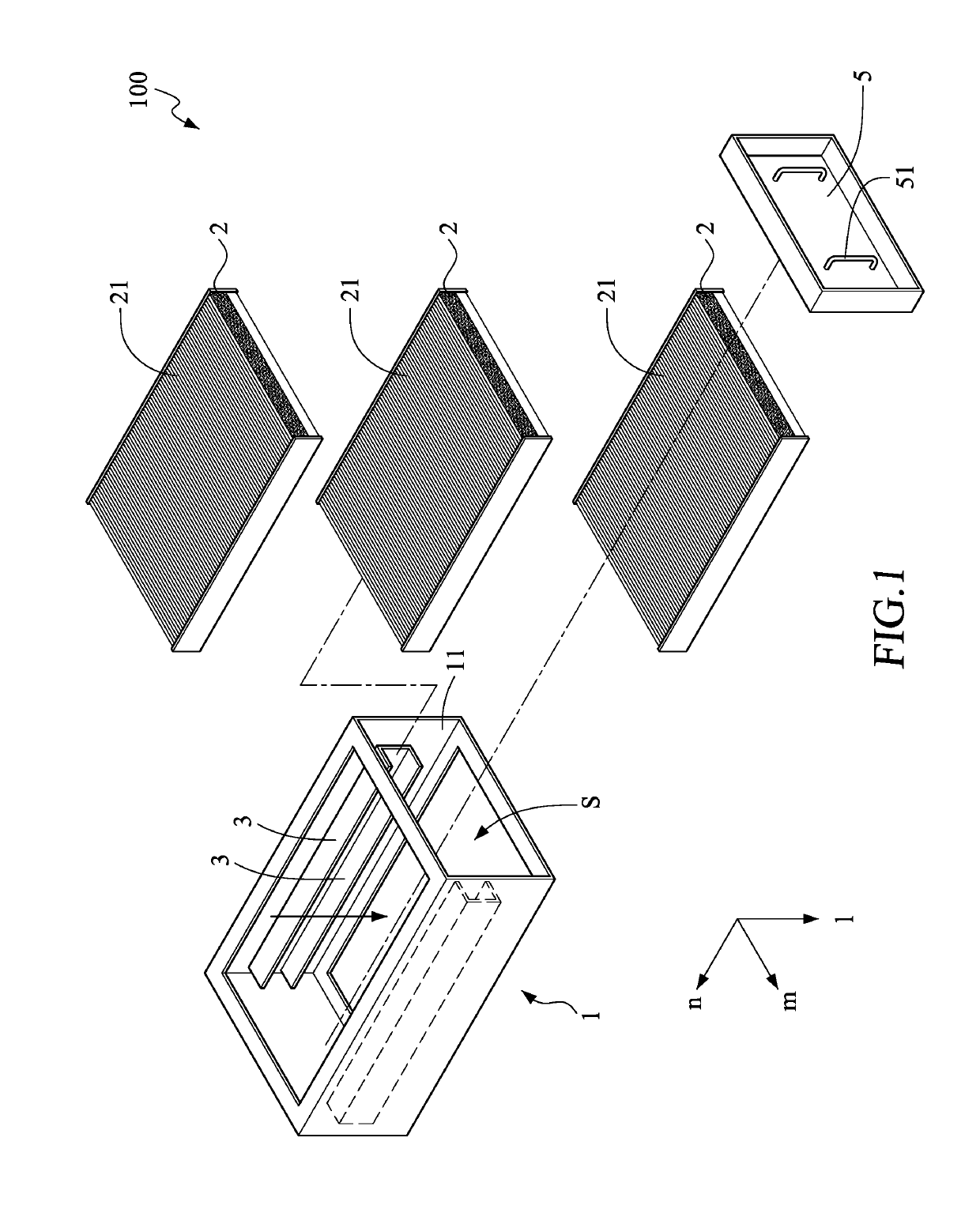
[0030]As shown in FIG. 1, a glue-free airtight filtering equipment 100 according to the present invention includes a filter housing 1, a plurality of filter elements 2 and a plurality of receiving supporting elements 3.

[0031]The filter housing 1 has a filtering space S, and an air flow passage, as indicated by an arrow in FIG. 1, is formed by an upper surface, a bottom surface and the filtering space S of the filter housing 1. In this embodiment, a fan is disposed below the filter housing 1 to evacuate the filtering space S, so that an air flow passes through the filter housing 1 from top to bottom via the air flow passage.

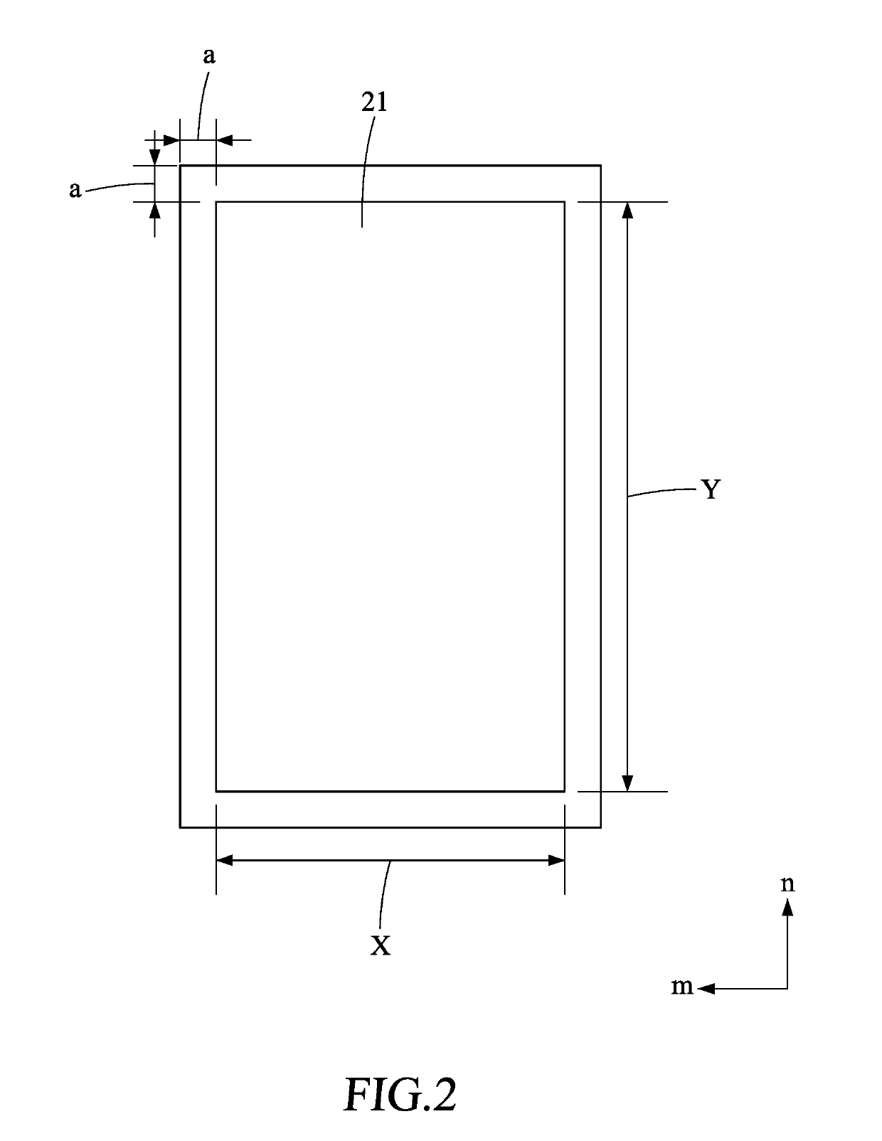
[0032]The plurality of filter elements 2, each having a filtering surface 21, are detachably disposed in the filtering space S in a manner that the filtering surface 21 is parallel to the upper surface and the bottom surface of the filter housing 1. Specifically, in this embodiment, the air flow passage is formed by the upper surface, the bottom surface and the fi...

second embodiment

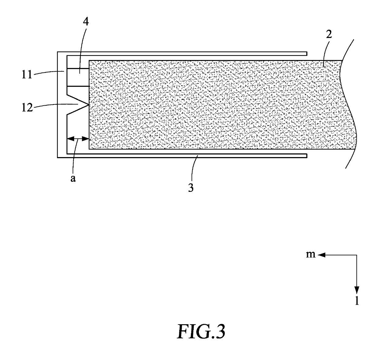
[0067]As shown in FIG. 4, in the present invention, the gap is a non-linear gap sandwiched between the inner wall 11 of the filter housing 1 and the filter element 2. Specifically, the filter element 2 is provided at a side thereof with an edge portion 22 having an undulating surface in shape correspondence to the inner wall 11 so as to form the non-linear gap in a direction (the direction l) parallel to the air flow passage. In this way, it can further prevent the air flow from passing through the gap without hindering the installation of the filter element 2, thereby reducing the leakage. The edge portion 22 may be a hard material such as a frame of the filter element 2, or may be a soft or compressible material, and the present invention is not limited thereto.

[0068]As mentioned above, compared with a prior art, the glue-free airtight filtering equipment 100 can meet the strict requirements of the gas leakage in the industry, and has various advantages of reducing resource cost a...

third embodiment

[0069]Furthermore, the present invention is provided. As shown in FIG. 5 and FIG. 6, a glue-free airtight filtering equipment 100a in the present invention includes a filter housing 1, a plurality of filter elements 2, a plurality of receiving supporting elements 3a, a cover 5 and a fastener 6.

[0070]The filter housing 1 has a filtering space S and a predetermined filtering direction (as indicated by an arrow in FIG. 5 and FIG. 6). In this embodiment, a fan is disposed below the filter housing 1 to evacuate the filtering space S, so that an air flow passes through the filter housing 1 from top to bottom along the filtering direction.

[0071]The plurality of receiving supporting elements 3a are provided to receive and support the plurality of filter elements 2. The plurality of receiving supporting elements 3a are installed in parallel in the filtering space S and are spaced apart from each other with a designated distance, and the filter elements 2 are slidably disposed one by one at t...


PUM

PropertyMeasurementUnit
air densityaaaaaaaaaa
pressureaaaaaaaaaa
widthaaaaaaaaaa

Abstract

Disclosed is glue-free airtight filtering equipment comprising a filter housing, a plurality of filter elements and a plurality of receiving supporting elements, each filter element having a filtering surface, the plurality of filter elements being detachably disposed in the filtering space in a manner that the filtering surface is parallel to the upper surface and the bottom surface of the filter housing, and the plurality of receiving supporting elements allocating on an inner wall of the filter housing and being spaced apart from each other with a designated distance so as to correspondingly receive and support the plurality of filter elements, wherein a gap is provided between the filter element and the inner wall of the filter housing, and the filtering surface of the filter element and the maximum value of the gap satisfy a relational expression.

Description

CROSS-REFERENCE TO RELATED APPLICATIONS[0001]This application claims priority to Taiwanese Application No. 106141266 (application for Invention patent), filed on Nov. 28, 2017, which is incorporated herein by reference in its entirety. This application also claims priority to Taiwanese Application No. 106217637 (application for Utility Model patent), filed on Nov. 28, 2017, which is incorporated herein by reference in its entirety.FIELD OF THE INVENTION[0002]The present invention relates to a filtering equipment, and more particularly relates to a glue-free airtight filtering equipment.BACKGROUND OF THE INVENTION[0003]In the field of industrial manufacturing, especially in the semiconductor manufacturing industry, in order to further improve the product yield, clean rooms are widely used for manufacturing products in a clean and pollution-free environment. A filtering equipment, which is a necessary and important facility to achieve cleanliness requirements for the clean room, is im...

Claims


Application Information

Patent Timeline
Patent Type & Authority Applications(United States)
IPC IPC(8): B01D46/00B01D46/10B01D46/12
CPCB01D46/0006B01D46/10B01D46/125B01D46/0023B01D46/0004B01D2265/06B01D2267/30B01D2267/70B01D46/121B01D46/62B01D46/0005B01D46/0039B01D46/56
Inventor HUANG, MING-WENYU, YI-HUI
Owner GREENFILTEC PTE LTD
Why Eureka
Try Eureka