Control apparatus for vehicle drive-force transmitting apparatus

Active Publication Date: 2019-05-30
TOYOTA JIDOSHA KK
View PDF0 Cites 2 Cited by
  • Summary
  • Abstract
  • Description
  • Claims
  • Application Information

AI Technical Summary

Benefits of technology

The present invention aims to provide a control apparatus for a vehicle drive-force transmitting apparatus that can reduce the uncomfortable feeling given to the vehicle operator during the shift-up action. The control apparatus is designed to switch between the first and second drive-force transmitting paths, and aims to minimize the discomfort caused by the gear mechanism and continuously-variable transmission that are used in such a drive-force transmitting apparatus.

Problems solved by technology

In this case, if the gear ratio of the continuously-variable transmission mechanism does not correspond to the highest gear ratio value upon determination for the execution of the shift-up action, the execution of the shift-up action is not started until the gear ratio of the continuously-variable transmission mechanism becomes the highest gear ratio value, thereby causing a time lag between the operator's operation and the execution of the shift-up action, and possibly giving a uncomfortable feeling to the operator.
However, since the rotational speed of the drive force source is not reduced until the execution of the shift-up action, an uncomfortable feeling could be given to the operator.

Method used


Image

  • Control apparatus for vehicle drive-force transmitting apparatus
  • Control apparatus for vehicle drive-force transmitting apparatus
  • Control apparatus for vehicle drive-force transmitting apparatus

Examples


first embodiment

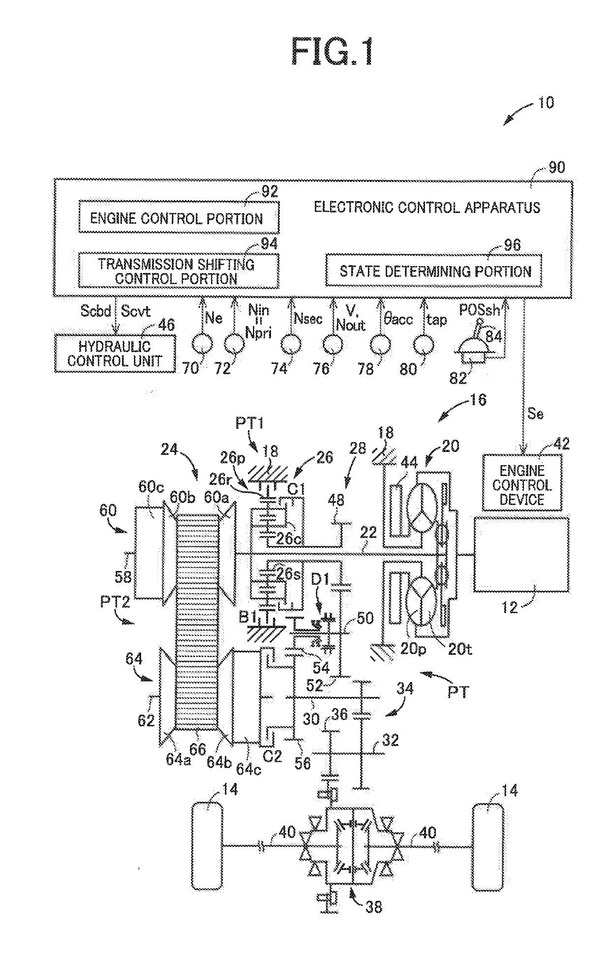
[0039]FIG. 1 is a schematic view showing a construction of a vehicle 10 to be controlled by a control apparatus according to the present invention, and major control functions and control portions of the control apparatus. As shown in FIG. 1, the vehicle 10 is provided with an engine 12 functioning as a drive force source configured to generate a drive force, drive wheels 14 and a drive-force transmitting apparatus 16 that is provided in drive-force transmitting paths between the engine 12 and the drive wheels 14.

[0040]The drive-force transmitting apparatus 16 includes a non-rotary member in the form of a casing 18, a fluid-operated type drive-force transmitting device in the form of a known torque converter 20 that is connected to the engine 12, an input shaft 22 connected to the torque converter 20, a continuously-variable transmission mechanism 24 connected to the input shaft 22, a forward / reverse switching device 26 connected to the input shaft 22, a gear mechanism 28 which is p...

second embodiment

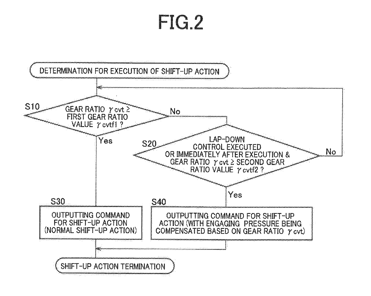
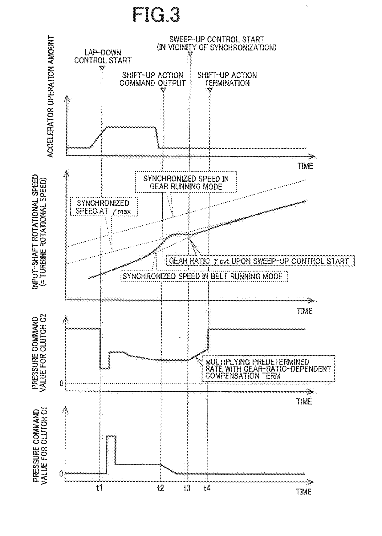
[0099]In the lap-down control executed in the above-described first embodiment, due to a limitation in control which could be caused by, for example, a shortage of amount of flow of the working fluid, the stepless shift-down action, by which the gear ratio γcvt of the continuously-variable transmission mechanism 24 is increase to the highest gear ratio value γmax, could not be satisfactorily performed. For example, there could be a situation in which the gear ratio γcvt is not increased to the highest gear ratio value γmax in the continuously-variable transmission mechanism 24, and even a situation in which the gear ratio γcvt is reduced as if a shift-up action were intended to be executed in the continuously-variable transmission mechanism 24. If it is determined that the lap-down control is executed even with such a situation in the execution of the stepless shift-down action in the continuously-variable transmission mechanism 24, the stepped shift-up action could be executed in t...


PUM


Abstract

A control apparatus for a vehicle drive-force transmitting apparatus which establishes selectively a first state in which a drive force is transmitted by a gear mechanism and a second state in which the drive force is transmitted by a continuously-variable transmission mechanism. The control apparatus executes a shift-up action requiring the first state to be switched to the second state, in (a) a case in which a state of the drive-force transmitting apparatus satisfies a first condition that a gear ratio of the continuously-variable transmission mechanism is not lower than a first gear ratio value and in (b) a case in which the state of the drive-force transmitting apparatus satisfies a second condition that a lap-down control is executed with the gear ratio of the continuously-variable transmission mechanism being not lower than a second gear ratio value that is lower than the first gear ratio value.

Description

[0001]This application claims priority from Japanese Patent Application No. 2017-226320 filed on Nov. 24, 2017, the disclosure of which is herein incorporated by reference in its entirety.FIELD OF THE INVENTION[0002]The present invention relates to a control apparatus for a drive-force transmitting apparatus that is to be provided in a vehicle, wherein the drive-force transmitting apparatus has a plurality of drive-force transmitting paths that are provided in parallel with each other between a drive force source and drive wheels of the vehicle.BACKGROUND OF THE INVENTION[0003]There is known a control apparatus for a drive-force transmitting apparatus that is to be provided in a vehicle having a drive force source and drive wheels, wherein the drive-force transmitting apparatus includes: an input rotary member to which a drive force is to be transmitted from the drive force source; an output rotary member from which the drive force is to be outputted to the drive wheels; a continuou...

Claims


Application Information

Patent Timeline
IPC IPC(8): F16H61/70F16H37/08
CPCF16H61/702F16H37/0846F16H2037/0866F16H61/66F16H37/022
Inventor KATO, SATOSHIMORITOMO, SUSUMUOWATARI, MASAKAZUTSUKAMOTO, NORIHIRO
Owner TOYOTA JIDOSHA KK
Why Eureka
Try Eureka