Braking control method, braking system and vehicle

Active Publication Date: 2020-06-25
ACER INC
View PDF16 Cites 1 Cited by
  • Summary
  • Abstract
  • Description
  • Claims
  • Application Information

AI Technical Summary

Benefits of technology

[0008]Based on the above, after the delay time of the braking signal and the preparation time for performing the braking operation according to the braking signal by the braking system are considered, the deceleration information and the corresponding braking s

Problems solved by technology

If the delay is more serious, it may cause passengers to feel uncomfortable during t

Method used


Image

  • Braking control method, braking system and vehicle
  • Braking control method, braking system and vehicle

Examples


Embodiment Construction

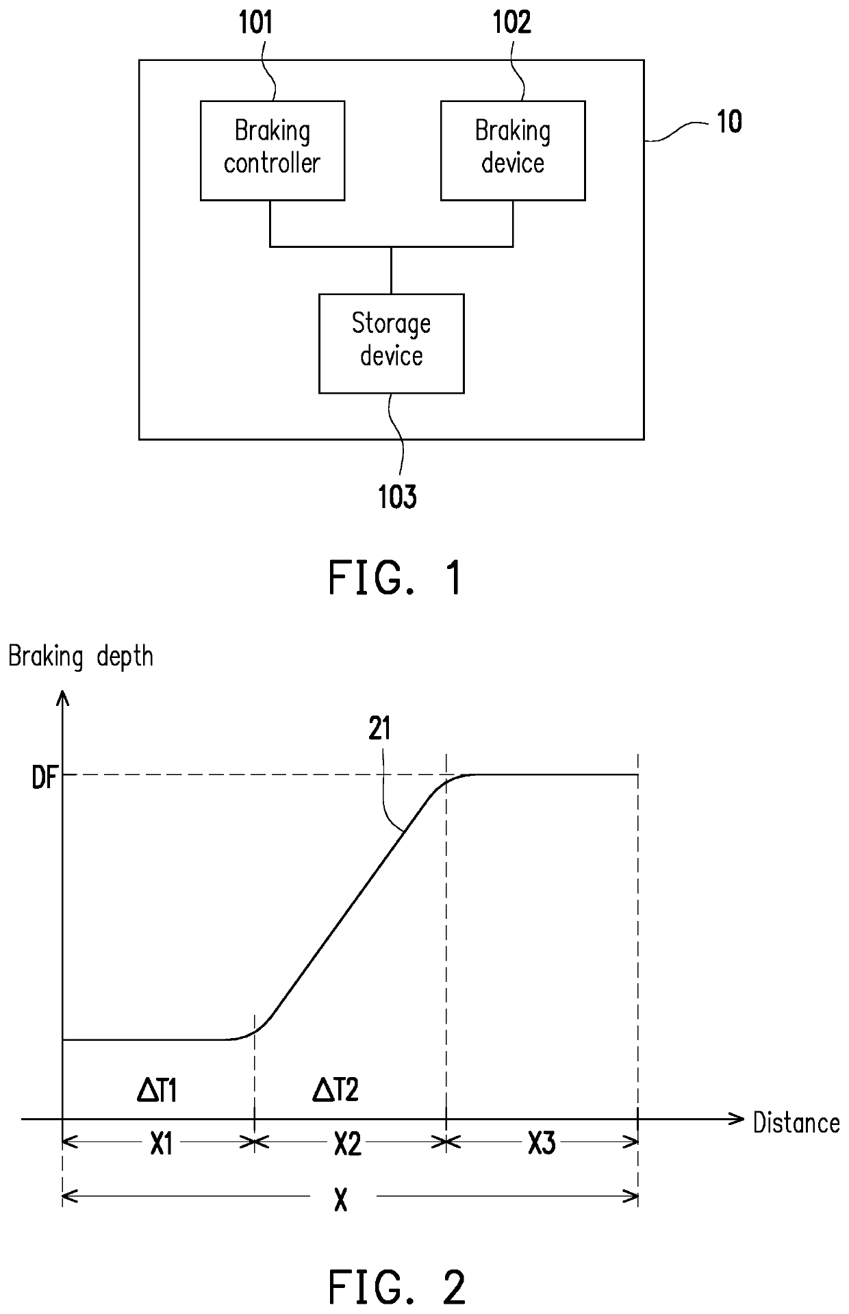
[0014]FIG. 1 is a schematic diagram of a braking system according to an embodiment of the disclosure. Referring to FIG. 1, in an embodiment, a braking system 10 may be deployed in various types of vehicles, such as cars, buses, or trucks. In an embodiment, the braking system 10 may also be deployed in a transportation vehicle such as a MRT, a subway, or a train. The disclosure does not limit the type of vehicle in which the braking system 10 is equipped.

[0015]The braking system 10 includes a braking controller 101, a braking device 102, and a storage device 103. The braking controller 101 may be a central processing unit (CPU) or other programmable general purpose or special purpose microprocessor, digital signal processor (DSP), programmable controller, special application integrated circuit, programmable logic device or other similar devices or combinations of these devices. In an embodiment, the braking controller 101 may control the overall or partial operations of the braking s...


PUM


Abstract

A braking control method for a braking system of a vehicle is provided according to an exemplary embodiment of the disclosure. The braking control method comprises: obtaining a total braking distance and a first speed of the vehicle; obtaining braking delay information related to the braking system, wherein the braking delay information includes first time information and second time information, the first time information reflects a delay time of a braking signal, and the second time information reflects a preparation time for performing a braking operation according to the braking signal by the braking system; obtaining deceleration information according to the total braking distance, the first speed and the braking delay information; generating the braking signal according to the deceleration information; and performing the braking operation according to the braking signal.

Description

CROSS-REFERENCE TO RELATED APPLICATION[0001]This application claims the priority benefit of Taiwan application serial no. 107145787, filed on Dec. 19, 2018. The entirety of the above-mentioned patent application is hereby incorporated by reference herein and made a part of this specification.BACKGROUNDTechnical Field[0002]The disclosure relates to a braking control technology, and particularly relates to a braking control method, a braking system and a vehicle.Description of Related Art[0003]Automated driving of vehicles has gradually become the focus of future transportation technology, and braking systems are also very important in autonomous driving technology. In general, more sophisticated braking system will include more control elements, causing signal transmission and / or component operation to be delayed in the braking system. If the delay is more serious, it may cause passengers to feel uncomfortable during the braking process, or even cause a car accident if the braking fo...

Claims


Application Information

Patent Timeline
IPC IPC(8): B60W30/18B60W40/04B60W50/04B60W50/00B60W30/17
CPCB60W30/181B60W50/0098B60W40/04B60K2031/0025B60W50/045B60W30/18109B60W2510/18B60W2050/048B60W2520/04B60W30/17B60T7/22
Inventor KE, LIANG-YUCHENG, YU-MIN
Owner ACER INC
Why Eureka
Try Eureka