Imaging optical system, projection display device, and imaging apparatus

a projection display device and optical system technology, applied in the field of imaging optical systems, can solve the problem of not saying that the back focal length is sufficiently long, and achieve the effect of sufficient back focal length and favorable optical performan

Active Publication Date: 2019-05-30
FUJIFILM CORP
View PDF0 Cites 1 Cited by
  • Summary
  • Abstract
  • Description
  • Claims
  • Application Information

AI Technical Summary

Benefits of technology

[0021]According to the present invention, it is possible to provide an imaging optical system, a projection display device comprising the imaging optical system, and an imaging apparatus comprising the imaging optical system. The imaging optical system has a small F number, a sufficient back focal length ensured, and a favorable optical performance.

Problems solved by technology

However, the optical system described in U.S. Pat. No. 7,009,765A is not a system having a small F number, and it can not be said that the back focal length is sufficiently long.

Method used


Image

  • Imaging optical system, projection display device, and imaging apparatus
  • Imaging optical system, projection display device, and imaging apparatus
  • Imaging optical system, projection display device, and imaging apparatus

Examples


example 1

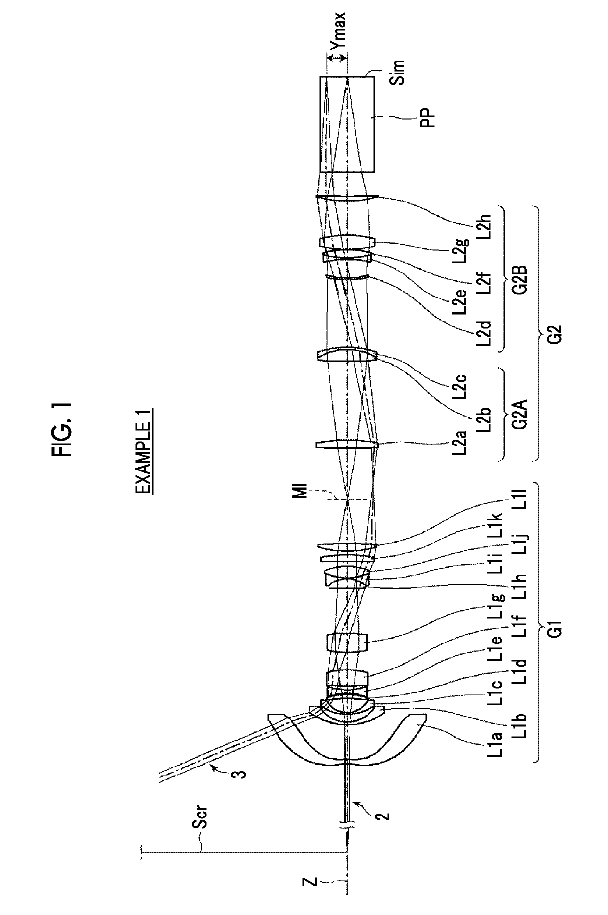
[0072]FIG. 1 is a cross-sectional view of the lens configuration and rays of an imaging optical system of Example 1, and a configuration and an illustration method thereof are as described above. Therefore, repeated descriptions are partially omitted herein. The imaging optical system of Example 1 consists of, in order from the magnification side to the reduction side: a first optical system G1 that has a positive refractive power; and a second optical system G2 that has a positive refractive power. The first optical system G1 consists of twelve lenses L1a to L1l in order from the magnification side to the reduction side. The second optical system G2 consists of a front group G2A and a rear group G2B in order from the magnification side to the reduction side. The front group G2A consists of three lenses L2a to L2c in order from the magnification side to the reduction side. The rear group G2B consists of five lenses L2d to L2h in order from the magnification side to the reduction sid...

example 2

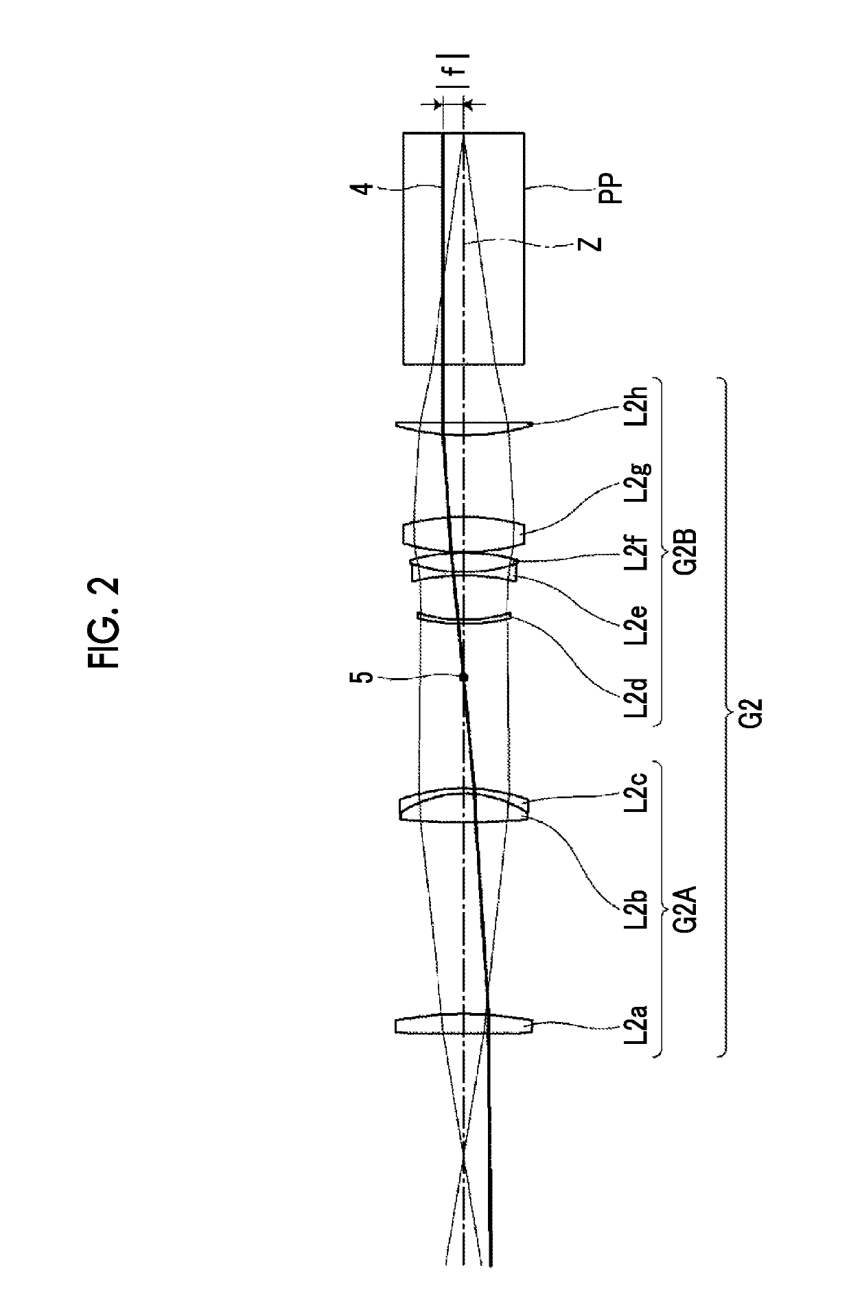
[0085]FIG. 2 is a cross-sectional view of a lens configuration and rays of an imaging optical system of Example 3. The imaging optical system of Example 2 consists of, in order from the magnification side to the reduction side: a first optical system G1 that has a positive refractive power; and a second optical system G2 that has a negative refractive power. The first optical system G1 consists of eleven lenses L1a to L1k in order from the magnification side to the reduction side. The second optical system G2 consists of a front group G2A and a rear group G2B in order from the magnification side to the reduction side. The front group G2A consists of three lenses L2a to L2c in order from the magnification side to the reduction side. The rear group G2B consists of four lenses L2d to L2g in order from the magnification side to the reduction side. The aspheric lens included in the first optical system G1 is the lens L1a.

[0086]Table 4 shows basic lens data of the imaging optical system ...

example 3

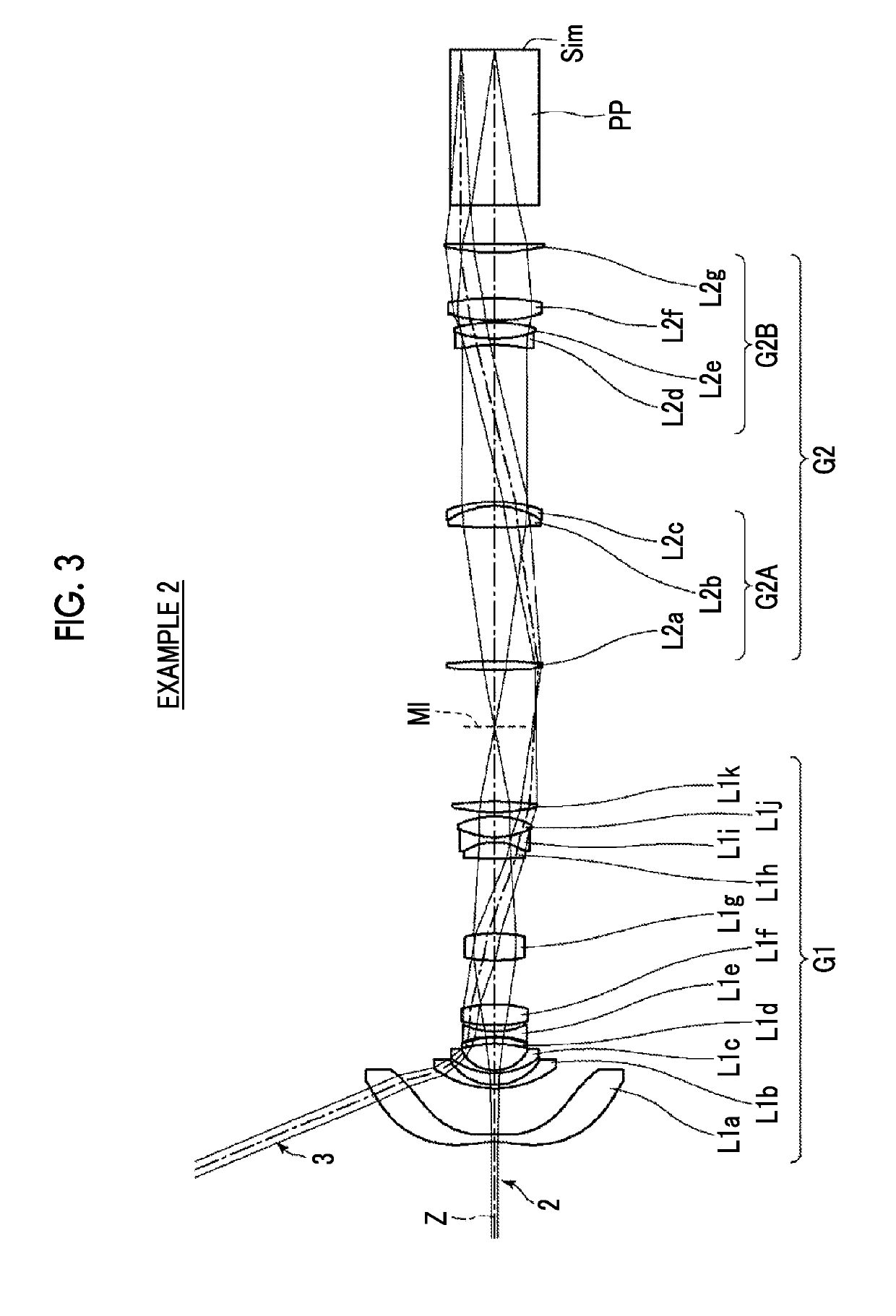
[0087]FIG. 3 is a cross-sectional view of a lens configuration and rays of an imaging optical system of Example 4. The imaging optical system of Example 3 consists of, in order from the magnification side to the reduction side: a first optical system G1 that has a positive refractive power; and a second optical system G2 that has a negative refractive power. The first optical system G1 consists of twelve lenses L1a to L1l in order from the magnification side to the reduction side. The second optical system G2 consists of a front group G2A and a rear group G2B in order from the magnification side to the reduction side. The front group G2A consists of three lenses L2a to L2c in order from the magnification side to the reduction side. The rear group G2B consists of four lenses L2d to L2g in order from the magnification side to the reduction side. The aspheric lenses included in the first optical system G1 are the lens L1a and the lens L1b.

[0088]Table 7 shows basic lens data of the ima...


PUM


Abstract

The imaging optical system consists of, in order from a magnification side: a first optical system which makes a magnification side imaging surface and an intermediate image conjugate to each other; and a second optical system which makes the intermediate image and a reduction side imaging surface conjugate to each other. The imaging optical system is configured to be telecentric on the reduction side. The first optical system includes an aspheric lens. The second optical system consists of a front group and a rear group. The imaging optical system satisfies predetermined conditional expressions for a focal length of the front group, a focal length of the imaging optical system, a focal length of the rear group, a maximum image height, a focal length of the first optical system, and the aspheric lens of the first optical system.

Description

CROSS-REFERENCE TO RELATED APPLICATIONS[0001]The present application claims priority under 35 U.S.C. § 119 to Japanese Patent Application No. 2017-229596, filed on Nov. 29, 2017. The above application is hereby expressly incorporated by reference, in its entirety, into the present application.BACKGROUND OF THE INVENTION1. Field of the Invention[0002]The present invention relates to an imaging optical system, a projection display device, and an imaging apparatus.2. Description of the Related Art[0003]In the past, projection display devices, each of which projects an image displayed on a light valve such as a liquid crystal display element or a Digital Micromirror Device (DMD: registered trademark) onto a screen or the like in an enlarged manner, have come into widespread use. In particular, some widely used devices adopt a configuration in which three light valves are used, illumination light beams with three primary colors of red, green, and blue respectively correspond to the light...

Claims


Application Information

Patent Timeline
Patent Type & Authority Applications(United States)
IPC IPC(8): G02B13/00H04N9/31G02B13/16H04N5/225
CPCG02B13/0045H04N9/317G02B13/16H04N5/2254H04N9/3105G02B13/22H04N23/55
Inventor NAGAHARA, AKIKO
Owner FUJIFILM CORP
Why Eureka
Try Eureka