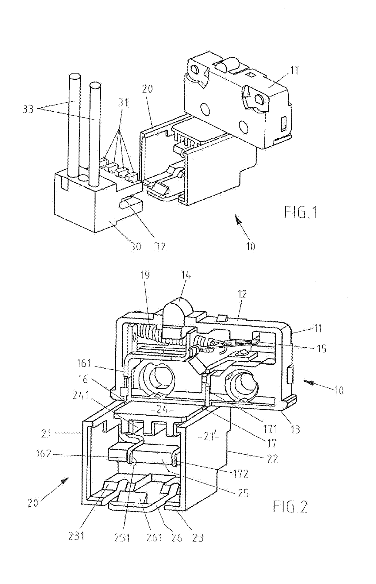
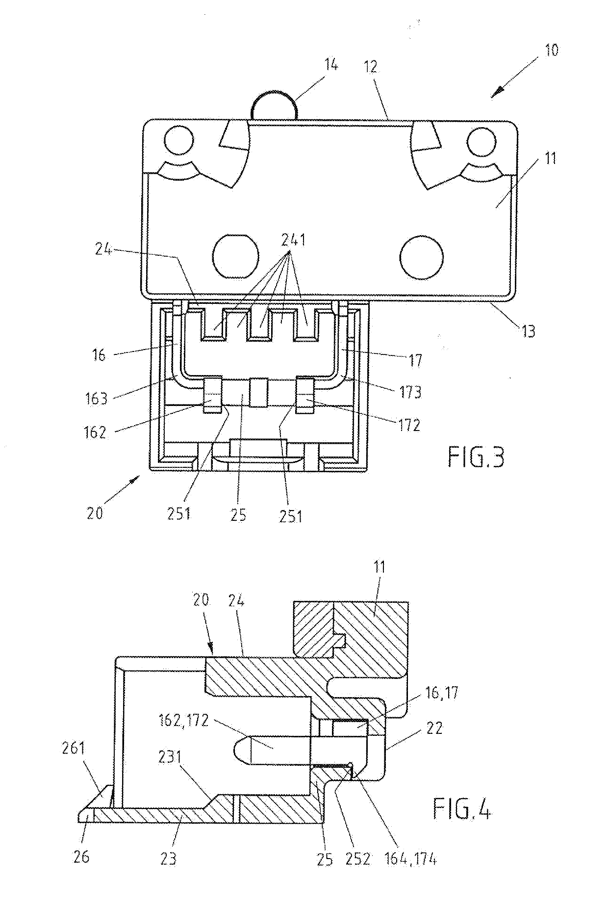
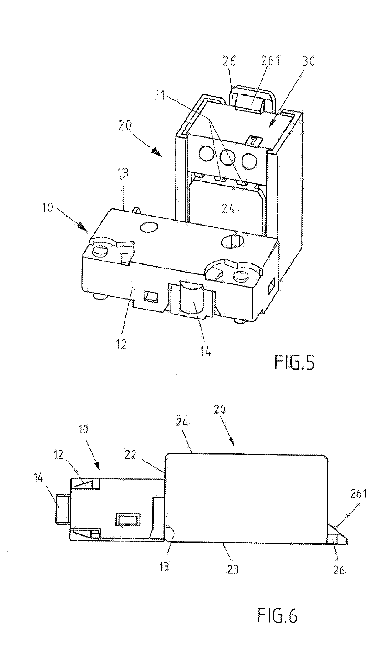
Electric switch

a technology of electric switch and switch housing, which is applied in the direction of contact, securing/insulating coupling contact member, electrical apparatus, etc., can solve the problems of less robust design of the switch, exposed live connections emerging from the switch housing, and cost-intensive procedures

Active Publication Date: 2019-06-13
JOHNSON ELECTRIC SA
View PDF14 Cites 0 Cited by
  • Summary
  • Abstract
  • Description
  • Claims
  • Application Information

AI Technical Summary

Benefits of technology

[0005]Accordingly, there is a d...

Problems solved by technology

This procedure is cost-intensive.
The disadvantage of this well-known snap-action switch with trough is the less robust design of this switch.
In addition, the live connections emerging fr...

Method used


Image

  • Electric switch
  • Electric switch
  • Electric switch

Examples


Embodiment Construction

[0027]The technical solutions of the embodiments of the present invention will be clearly and completely described as follows with reference to the accompanying drawings. Apparently, the embodiments as described below are merely part of, rather than all, embodiments of the present invention. Based on the embodiments of the present invention, any other embodiment obtained by a person skilled in the art without paying any creative effort shall fall within the protection scope of the present invention.

[0028]It is noted that, when a component is described to be “fixed” to another component, it can be directly fixed to the another component or there may be an intermediate component. When a component is described to be “connected” to another component, it can be directly connected to the another component or there may be an intermediate component. When a component is described to be “disposed” on another component, it can be directly disposed on the another component or there may be an in...


PUM


Abstract

The invention relates to an electric switch for electric appliances. The electric switch include a switch housing, an actuating element, and a plug socket. The actuating element is configured to switch a contact system accommodated in the switch housing by movement between a switch-off position and a switch-on position. The plug socket is non-detachably connected to the switch housing. Electrical connections of the contact system are held in the plug socket such that ends of the electrical connections are in predetermined positions.

Description

CROSS REFERENCE TO RELATED APPLICATIONS[0001]This non-provisional patent application claims priority under 35 U.S.C. § 119(a) from Patent Application No. 10 2017 129 515.1 filed in Germany on Dec. 12, 2017.FIELD OF THE INVENTION[0002]The present invention relates to an electric switch for an electric appliance, in particular an electric switch which is suitable to be connected to a RAST connector.BACKGROUND OF THE INVENTION[0003]RAST connectors are standardized connectors of the so-called household appliance standards RAST 2.5 and RAST 5. The abbreviation RAST stands for the German term Raster-Anschluss-Steck-Technik (pitch connection plug technology), and the numbers stand for the distance in millimeters between the contacts. This standardized RAST plug connector was developed in close coordination between the most important household appliance manufacturers. Such a RAST plug connector makes it possible to simply replace the components in the event of repairs. For well-known electr...

Claims


Application Information

Patent Timeline
IPC IPC(8): H01H13/26H01R13/627H01R13/70
CPCH01H13/26H01R13/6277H01R13/70H01R13/41H01R13/6272H01H1/5866H01H13/10
Inventor KUNZ, ALEXANDERKEMSKI, MARKUS
Owner JOHNSON ELECTRIC SA
Why Eureka
Try Eureka