Auto laundry conveyor dolly

a conveyor and dolly technology, applied in the field of auto laundry conveyor dolly, can solve the problems of reducing the lifespan of the dolly, reducing the service life of the dolly, so as to achieve the effect of reducing the component count and sturdy design of the dolly

Inactive Publication Date: 2011-04-21
SWANSON IND
View PDF4 Cites 1 Cited by
  • Summary
  • Abstract
  • Description
  • Claims
  • Application Information

AI Technical Summary

Benefits of technology

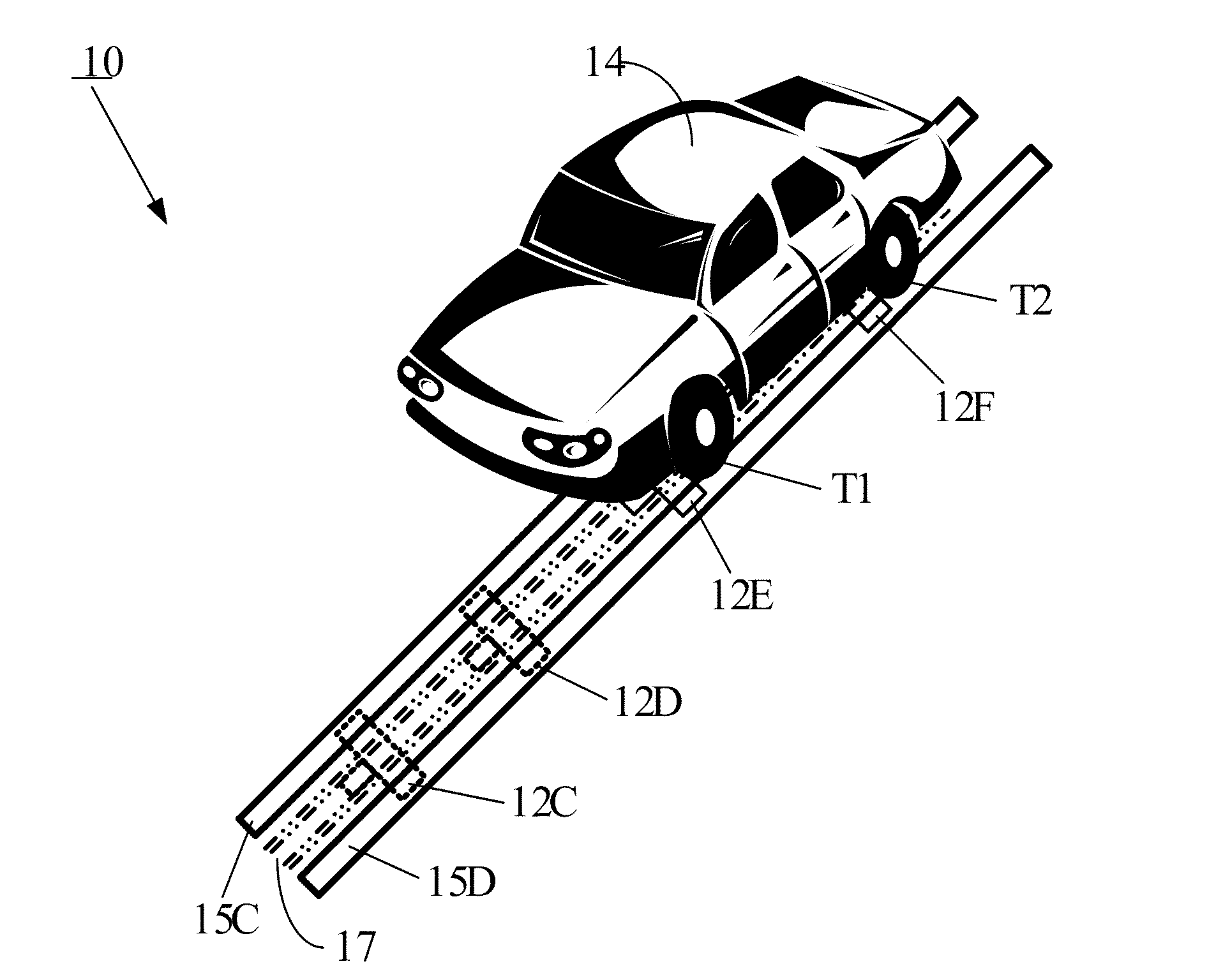
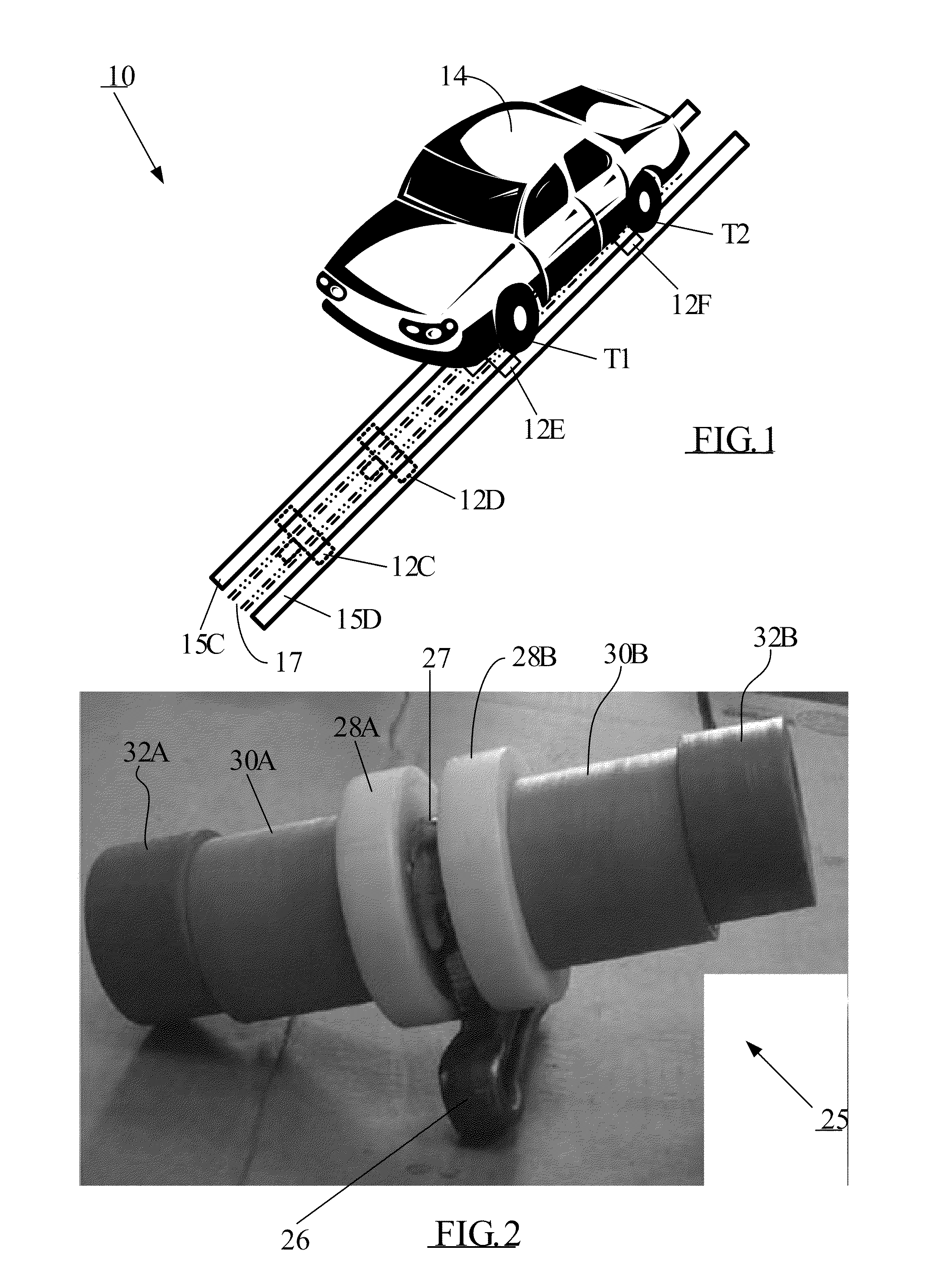
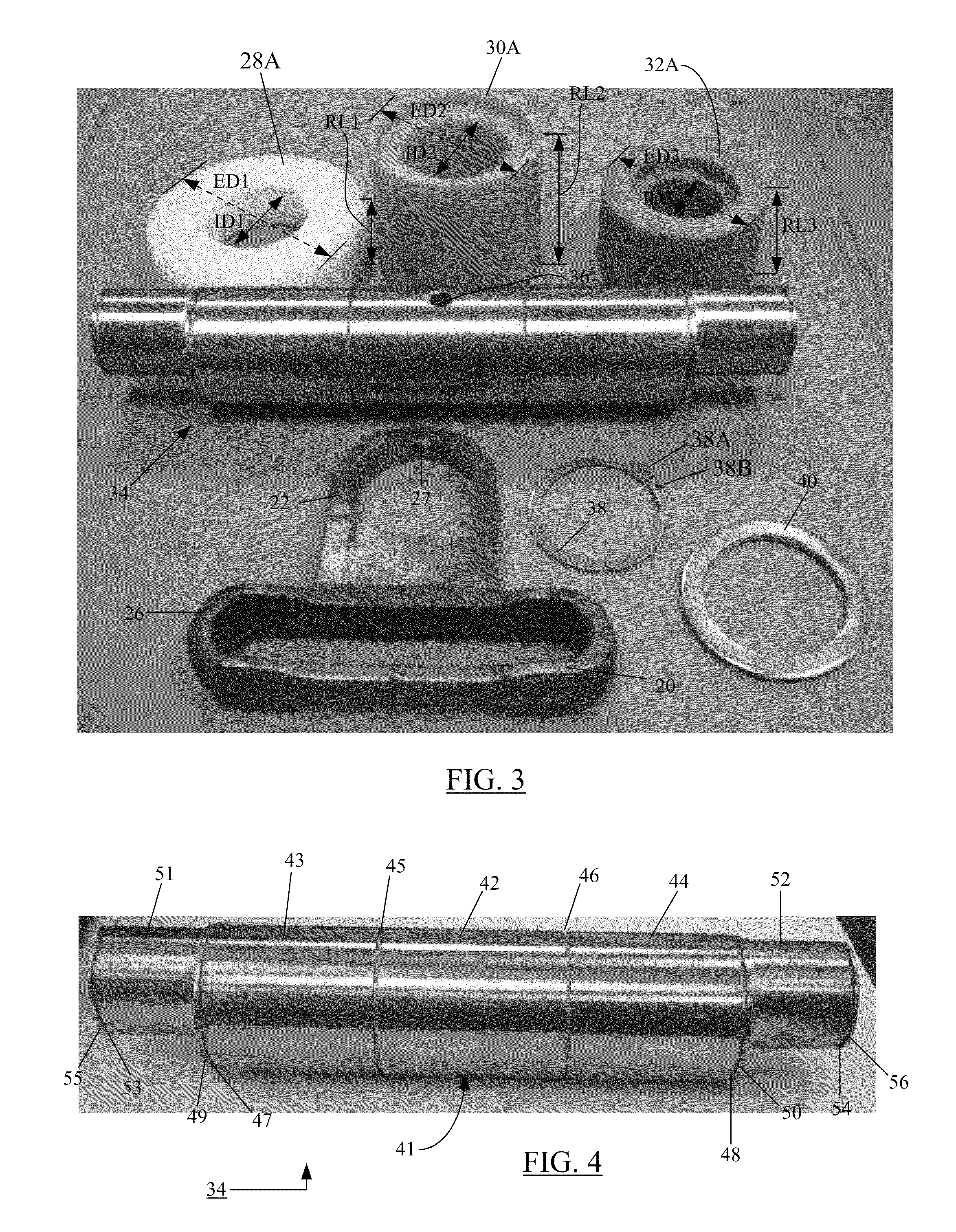
[0008]In one embodiment, the present disclosure relates to a car wash dolly having a stronger camshaft with bolt-less design and minimized component count. The center link and wheels may be mounted directly on the shaft to produce a sturdy design for the dolly. Grooves and snap rings are provided to keep wheels close to one another to prevent dirt or other debris from getting between the wheels. The dolly is intended to roll, via a conveyor chain, on a slotted track of a car wash system.

Problems solved by technology

This arrangement frequently leads to bending of the bolt during operation, thereby necessitating removal and replacement of the damaged dollies.
Furthermore, the bolt and nut engagement may become lose under certain operational conditions.
Hence, the bolt-based dolly design may be commercially undesirable because it leads to a reduced lifespan of the dolly, resulting in expensive repairs / replacements.

Method used


Image

  • Auto laundry conveyor dolly
  • Auto laundry conveyor dolly
  • Auto laundry conveyor dolly

Examples


Embodiment Construction

[0027]The accompanying figures and the description that follows set forth the present disclosure in embodiments of the present disclosure. However, it is contemplated that persons generally familiar with mechanical designs, and more particularly with designs of car wash dollies, will be able to apply the teachings of the present disclosure in other contexts by modification of certain details. Accordingly, the figures and description are not to be taken as restrictive of the scope of the present disclosure, but are to be understood as broad and general teachings. In the discussion herein, when any numerical value is referenced, such value should be understood to be the most practically-feasible design approximation taking into account variances that may be introduced by such mechanical operations as machining, tooling, drilling, etc.

[0028]It is observed at the outset that the directional terms such as “top,”“bottom,”“right,”“left,”“horizontal,”“vertical,”“upper,”“lower,” etc., and de...


PUM


Abstract

A car wash dolly that uses a single shaft having two camshaft lobes and a series of snap ring grooves. The bolt-less design of the dolly includes a stronger camshaft and minimized component count. The center link and wheels may be mounted directly on the shaft to produce a sturdy design for the dolly. Grooves and snap rings are provided to “lock” wheels in their place on the shaft and to keep wheels physically close to one another to prevent dirt or other debris from getting between the wheels. Optional thrust washers also may be provided between plastic wheels and snap rings to reduce friction between the wheels during operation of the dolly in a car wash facility. The dolly according to the present disclosure is intended to roll, via a conveyor chain, on a slotted track of an auto-laundry system. Because of rules governing Abstracts, this Abstract should not be used to construe the claims in this patent application.

Description

BACKGROUND[0001]1. Field of the Disclosure[0002]The present disclosure generally relates to the field of auto-laundry systems of the type employing an endless loop chain conveyor linking a plurality of car-pusher dollies that roll along slotted tracks, and, more particularly, to a car wash dolly design that uses a single, solid shaft with two camshaft lobes and a series of snap ring grooves.[0003]2. Brief Description of Related Art[0004]Certain auto-laundry systems, otherwise popularly known as “car washes,” use endless chain conveyors of the type having “dollies” linked into the continuous-loop chain of a conveyor at regular intervals. These dollies are used to push vehicles along a track by engaging the tread surface of the tires of the vehicle. The dollies, in turn, are connected into the continuous loop chain by means of a center link.[0005]The track structure which is used in combination with the chain and the dollies typically comprises three separate tracks mounted in paralle...

Claims


Application Information

Patent Timeline
Patent Type & Authority Applications(United States)
IPC IPC(8): B61J3/04B61B10/00B60S3/04
CPCB61B10/04B60S3/004
Inventor SMOCK, DANIEL D.SIZER, JEFFERY A.
Owner SWANSON IND
Why Eureka
Try Eureka