Trussed girder for the construction industry and method for producing a trussed girder of this kind

a technology for girders and construction, which is applied in the direction of girders, trusses, joists, etc., can solve the problem that girders cannot be produced at a high cost, and achieve the effects of simple and less expensive production, high load-bearing capacity, and flexural rigidity

Active Publication Date: 2022-01-18
PERI AG
View PDF8 Cites 0 Cited by
  • Summary
  • Abstract
  • Description
  • Claims
  • Application Information

AI Technical Summary

Benefits of technology

[0003]The problem addressed by the invention is therefore that of providing a trussed girder which has a sufficiently high load-bearing capacity and flexural rigidity, is simple and less expensive to produce, and which is easy to handle. Furthermore, the problem addressed by the invention is that of providing a simplified and inexpensive production method, in particular for mass producing trussed girders.
[0006]Glued joints between the individual struts are omitted by using the strut run. As a result, it is possible to have fewer production steps and use less glue for the manufacture of the trussed girder. The raw wood material can be better utilized by using a wood-based material, since the high-quality pieces of solid wood are only used for the flanges, while even lower quality wood, which has knots for example, is still suitable for use in the wood-based material. The trussed girder can also, due to the predominant use of wood and wood-based material, be produced in an altogether resource-conserving manner and, upon reaching the lifespan thereof, also be disposed of in an environmentally friendly manner. The trussed girder is distinguished by a long lifespan as a result of the sturdy design. The identical radii of the undulating upper and underside of the strut run, as opposed to the usual concentric radii, also means that the strut run has a larger glued surface in the region of the flange, for an improved transmission of force, while the free struts between the flanges are narrower and therefore lighter than in conventional struts of the same width. This has two advantages. There is less waste in the production of the strut run, and a lower consumption of materials. Also, improved load-bearing properties can be achieved in the finished trussed girder of same weight, and a lower weight can be achieved in the trussed girder which has the same load-bearing properties.
[0007]The strut run preferably consists of a high-density wood fiber (board) material. Prefabricated, inexpensive, high-density (wood) fiber boards are available on the market in various sizes and are distinguished by a high load capacity and a high flexural rigidity. High-density wood fiber boards of this kind can also be designed to be sufficiently rot-proof for outdoor uses, using the relevant wood fiber bonding agent or the glue and the high level of compression of the wood fibers. It is self-evident that the wood fiber material can be additionally coated if required, in order to further increase the weather resistance thereof.
[0008]The strut run has lateral faces which are preferably, at least in portions, plane-parallel to one another. As a result, predefined flexural strength and torsional strength of the trussed girder can be more easily achieved and maintained. Furthermore, in the production of the trussed girder, the strut run can be cut from a wood fiber material board, in particular a high-density board, particularly easily and efficiently as a result.
[0009]The strut run preferably engages in grooves of the two flanges, each groove base of which forms a semi-circular profile in the longitudinal direction of the flange, lateral surfaces of the groove that extend in the longitudinal direction each including in particular an acute angle α, and the strut run then also including a corresponding acute angle α together with the mortised or dovetailed portion of the strut run that is glued to each of said lateral surfaces. As a result, a particularly stable and durable mortise or dovetail of the strut run with the flanges is achieved. During the production method of the trussed girder, glue applied to the lateral surfaces for mortising or dovetailing is not or is only slightly moved in the direction of the groove bases when the strut run is inserted into the grooves. The glue therefore remains on the surfaces which are to be bonded to one another, as a result of which enough glue remains for firm and durable gluing in place.
[0017]The method of production according to the invention is particularly suitable for mass-producing trussed girders in an inexpensive manner. The strut runs, as a result of the corresponding radii of the mutually facing, undulating upper and underside of said runs, can be cut from or out of the wood-based material boards without any significant waste. Based on a rectangular-shaped wood fibre board, unavoidable waste only needs to be taken into account on the two mutually facing edges of the fibre board in the extension direction of the wood fibre board. In this case an initial or final undulating cut is therefore required in order to define an undulating edge contour of the edge strut runs which are each to be cut from the fibre board at the edge. By means of the mutually corresponding radii of the cutting lines, each cutting line which is arranged between two further cutting lines in the extension direction of the (wood) fibre boards defines the undulating upper side of a first strut run and the undulating underside of a second strut run. Overall, the trussed girders can therefore be produced for a reduced outlay in terms of materials, cost and time. For the purpose of producing the strut runs, completely automated or computer-controlled cutting systems can be readily used, said systems advantageously comprising automatic feeding of the wood-based material boards. The trussed girders can be assembled in principle supported by robotics.

Problems solved by technology

Due to the complex structural design, however, the trussed girder can only be produced at a high expense.

Method used


Image

  • Trussed girder for the construction industry and method for producing a trussed girder of this kind
  • Trussed girder for the construction industry and method for producing a trussed girder of this kind
  • Trussed girder for the construction industry and method for producing a trussed girder of this kind

Examples


Embodiment Construction

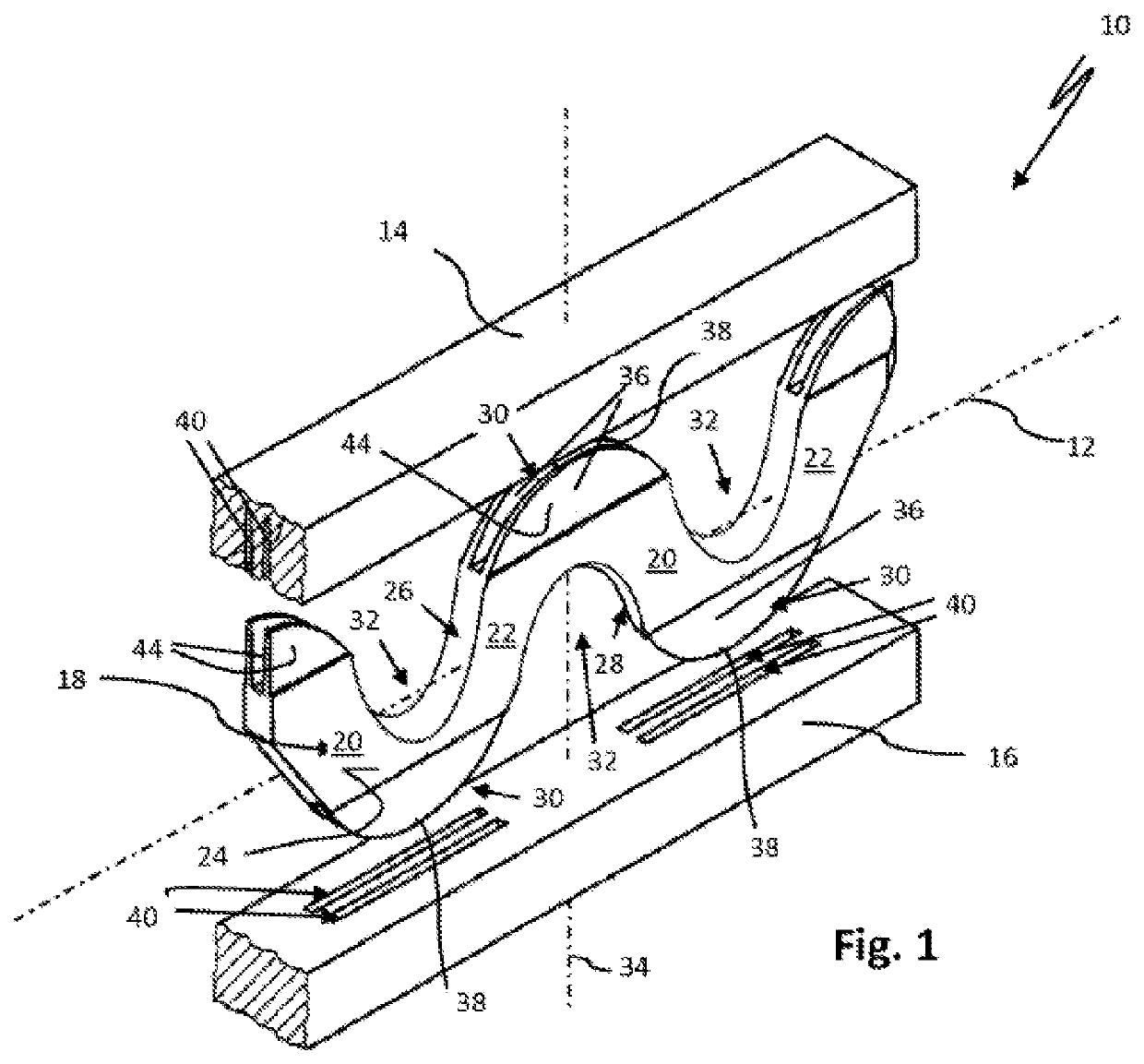
[0024]FIG. 1 shows an exploded perspective view of the components of a portion of a trussed girder 10 for the construction industry. The trussed girder 10 extends a few meters in the direction of the longitudinal axis 12 thereof and has dimensions which are common for a trussed girder of this kind in the construction industry. It is self-evident that the trussed girder 10 can be provided in special lengths, in particular for special constructions, as can be required in formwork for concrete ceilings or concrete walls.

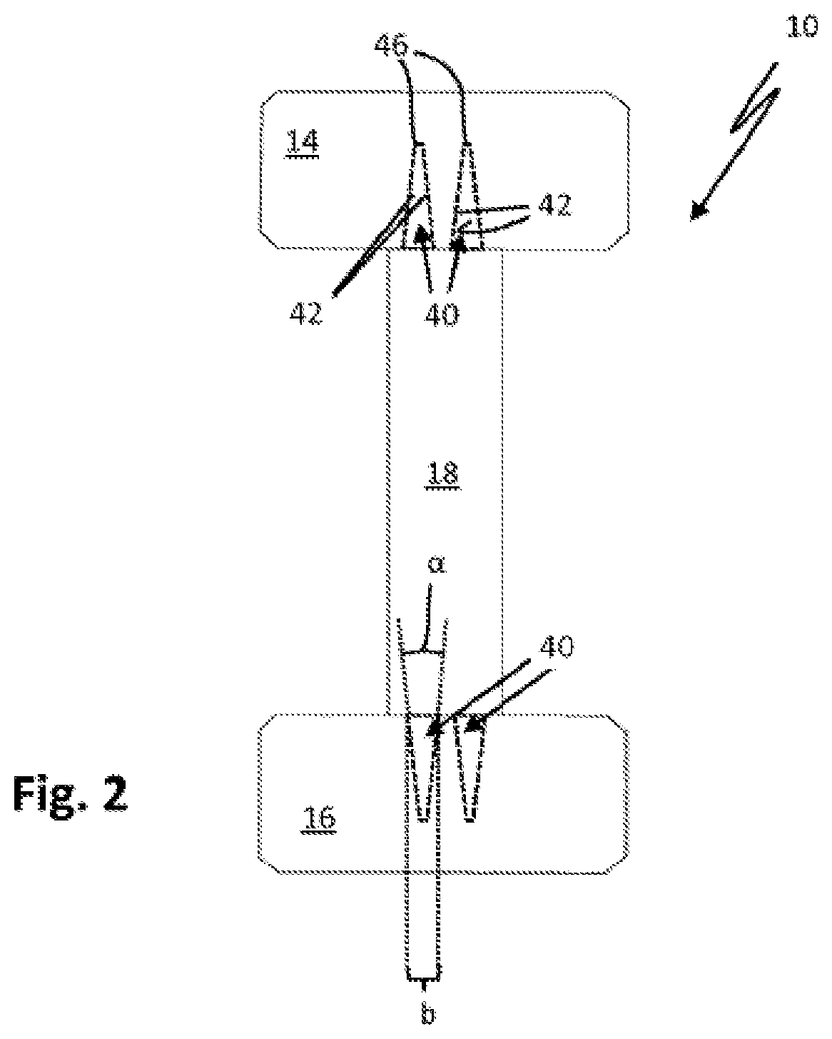
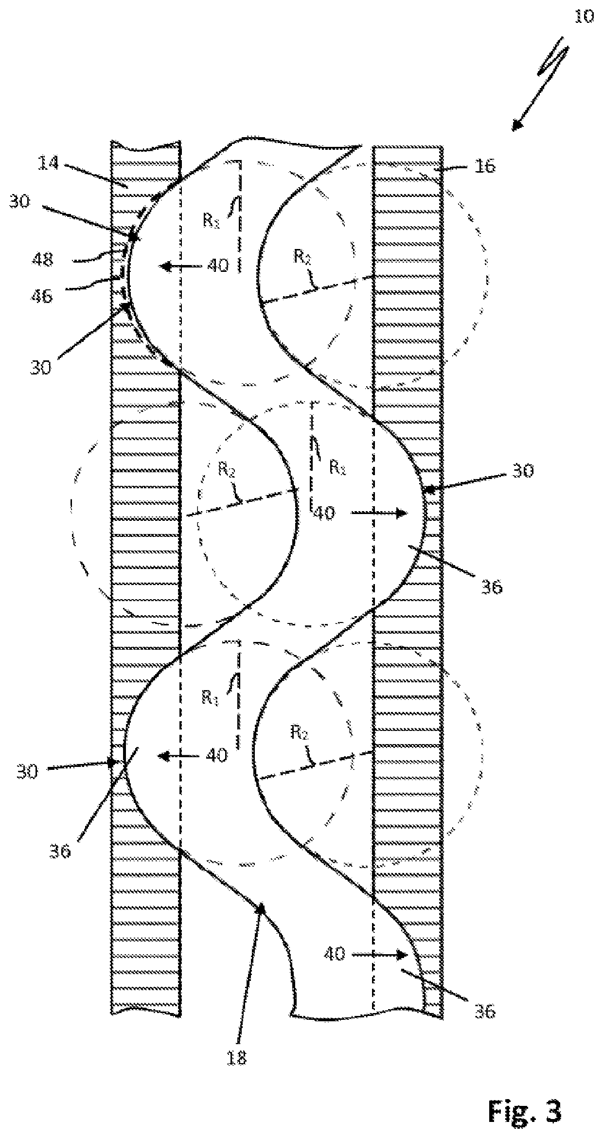
[0025]The trussed girder 10 has an upper flange 14 made from square timber and a lower flange 16 made from square timber. A strut run 18 which is formed as a single piece is used to connect the two flanges 14, 16. The strut run 18 is formed as a single-piece wood-base material board blank, in this case as a high-density fiber board blank. The strut run 18 therefore consists of a high-density wood fiber material.

[0026]The strut run has struts 20, 22, which are each arran...


PUM


Abstract

A trussed girder for the construction industry, having an upper flange and having a lower flange made of square timber, which extend along the longitudinal axis of the trussed girder and which are connected to one another by a plurality of struts, which are each arranged so as to extend obliquely to the flanges. The struts are formed by at least one strut run, the upper side and underside of which are formed in an undulating manner in the axial direction and are arranged so as to extend parallel to one another with radii corresponding to one another. The strut run is mortised or dovetailed in the axial direction alternately by means of the upper flange and the lower flange and is formed as a single-piece wood material part. The invention additionally relates to a method for producing trussed girders of this kind, in particular on a mass scale.

Description

FIELD OF THE INVENTION[0001]The invention relates to a trussed girder for the construction industry and a method for producing trussed girders of this kind.BACKGROUND OF THE INVENTION[0002]Trussed girders have long been established in building practice and are used in the concrete construction of wall formwork, column formwork and ceiling formwork. The trussed girders have an upper and a lower flange which extend along the longitudinal axis of the trussed girder. The two flanges are, according to one style of construction, connected to one another by struts arranged in the manner of a framework. The struts are each arranged so as to extend obliquely relative to the flanges. The trussed girders have to have as great a load-bearing capacity and flexural rigidity as possible, in order to minimise the number of supports, steel walers or ceiling props required to support the trussed girders during the operational use of said girders. Trussed girders are mass produced, often at least part...

Claims


Application Information

Patent Timeline
Patent Type & Authority Patents(United States)
IPC IPC(8): E04C3/16
CPCE04C3/16
Inventor MIKIC, ERZAD
Owner PERI AG
Why Eureka
Try Eureka