Municipal Mixing with Reciprocating Motion Disk

a technology of reciprocating motion and mixing disk, which is applied in the direction of mixing, transportation and packaging, and biological sludge treatment, etc., can solve the problem that the flow rate through the open area is too low for effective mixing, and achieve the effect of high flow rate and high velocity flow

Active Publication Date: 2019-06-20
OVIVO INC
View PDF11 Cites 0 Cited by
  • Summary
  • Abstract
  • Description
  • Claims
  • Application Information

AI Technical Summary

Benefits of technology

[0006]The mixing disk is essentially a flat annular plate, circular or polygonal in shape surrounding an open central area (“open area”), with the annulus of the ring having a specific “footprint” or closed area, designed to produce a high velocity flow through the open area during linear reciprocating travel of the mixing disk. If the open area is too large relative to the closed area (also considering stroke length and frequency), fluid velocity through open area can be too low for effective mixing. In an ideal design that center fluid velocity and flow rate are maximized.

Problems solved by technology

If the open area is too large relative to the closed area (also considering stroke length and frequency), fluid velocity through open area can be too low for effective mixing.

Method used


Image

  • Municipal Mixing with Reciprocating Motion Disk
  • Municipal Mixing with Reciprocating Motion Disk

Examples


Embodiment Construction

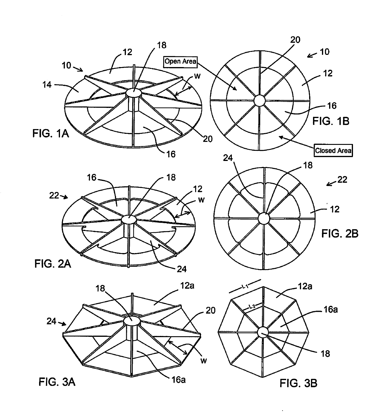
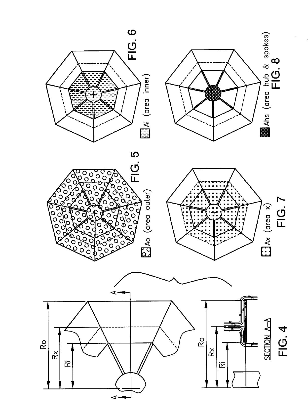
[0018]The drawings illustrate several different general configurations of reciprocating mixer disk to which the principles of the invention can be applied. FIGS. 1A and 1B show one pattern in the form of a mixing disk 10 comprised of an annular ring 12 of closed area that is shown flat, planar but which could be conical if desired, as in some mixer disks of the prior art. The flat ring 12 has outer and inner radii, Ro and Ri respectively, defining a width, Wdisk=Ro−Ri, closed area 14 (references to closed area herein include only the ring 12). In the center is an open area 16. If the solid ring 12 is sloped, in a conical shape, it is the projected area that is important to the invention, that is, the area that would be seen as the closed area 12 in plan view, such as seen in FIG. 1B.

[0019]The mixing disk has a hub 18 to which a reciprocating mixer shaft is attached concentrically, secured into either the hub side seen in FIG. 1A or the opposite side. A series of spokes or struts 20,...


PUM

PropertyMeasurementUnit
speedaaaaaaaaaa
speedaaaaaaaaaa
diameteraaaaaaaaaa

Abstract

A reciprocating motion disk for mixing wastewater in a tank of a treatment plan is optimized for geometry, along with cycling speed and stroke length, to cause effective mixing velocity throughout the tank.

Description

[0001]This application claims benefit of provisional application No. 62 / 304,042, filed Mar. 4, 2016.BACKGROUND OF THE INVENTION[0002]This invention is concerned with efficient mixing of liquids and slurries using a reciprocating motion to oscillate a mixing disk. In particular the invention is directed to increasing mixing performance and efficiency with optimized geometry in a mixing disk in a reciprocating mixer. An important application of the invention is in wastewater treatment, in the mixing of wastewater slurries, especially in digesters, such as anaerobic digesters.[0003]Linear motion mixers, i.e. reciprocating motion mixers, are described in U.S. Pat. Nos. 7,685,896, 7,399,112, 7,364,351, 7,278,781, 7,029,166, 6,830,369, 6,007,237, 5,100,242 and 5,052,813, as well as U.S. Pub. No. 2015 / 182927. These mixers, at least in the context of the current invention, typically are used in very large vessels, such as, for example, a mixing disk of six feet operating in a vessel about 5...

Claims


Application Information

Patent Timeline
Patent Type & Authority Applications(United States)
IPC IPC(8): C02F3/28B01F11/00
CPCC02F3/28B01F11/0082B01F2215/0454B01F2215/0052B01F2215/0481B01F2215/0431C02F11/04B01F31/441B01F2101/305
Inventor GOLDHARDT, JAMESCHRISTIANSEN, HAYDON
Owner OVIVO INC
Why Eureka
Try Eureka