
Modulating retroreflective piezoelectric multilayer film

Active Publication Date: 2019-06-20
ANDREW SIMON FILO
View PDF0 Cites 4 Cited by
  • Summary
  • Abstract
  • Description
  • Claims
  • Application Information

AI Technical Summary

Benefits of technology

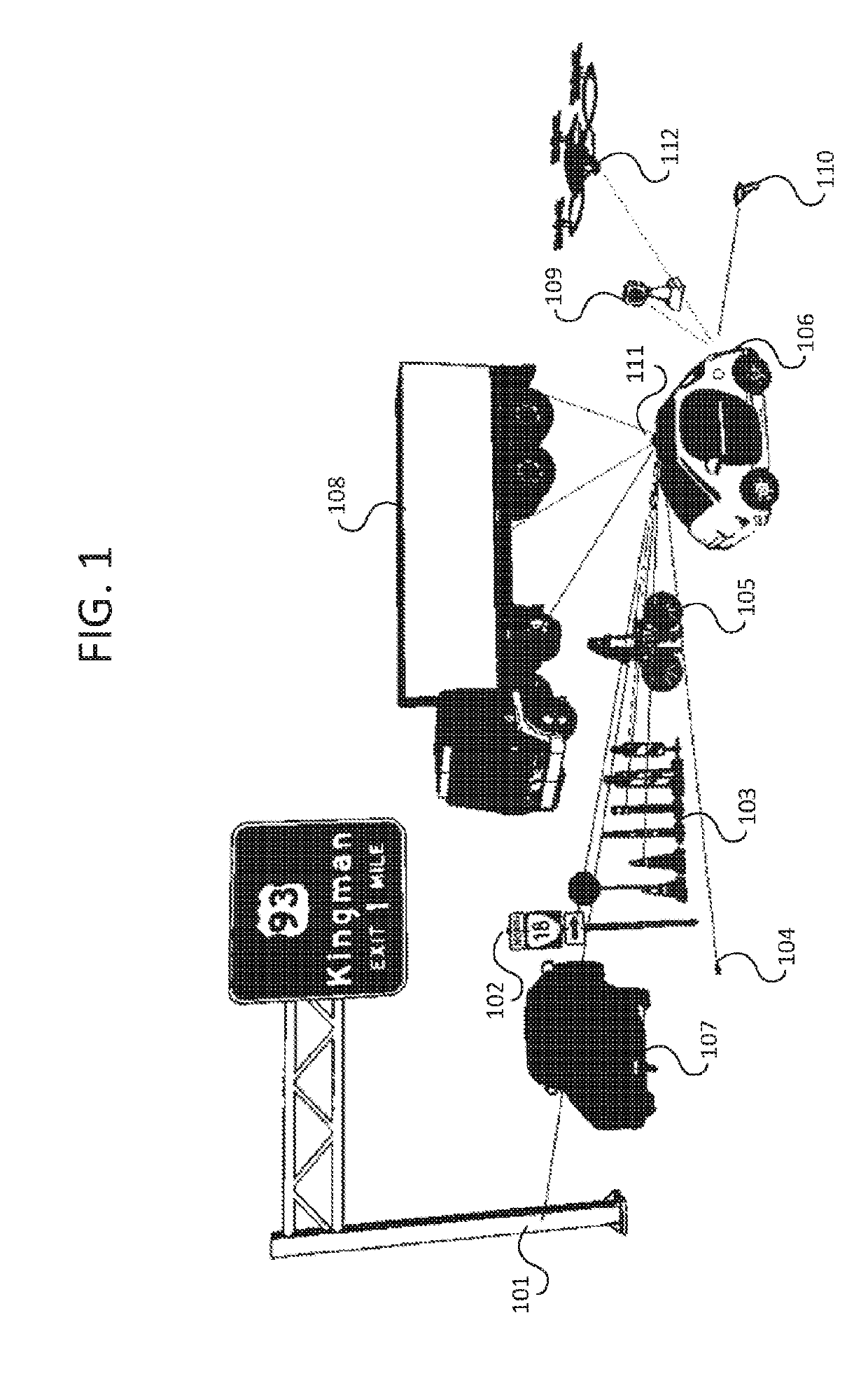
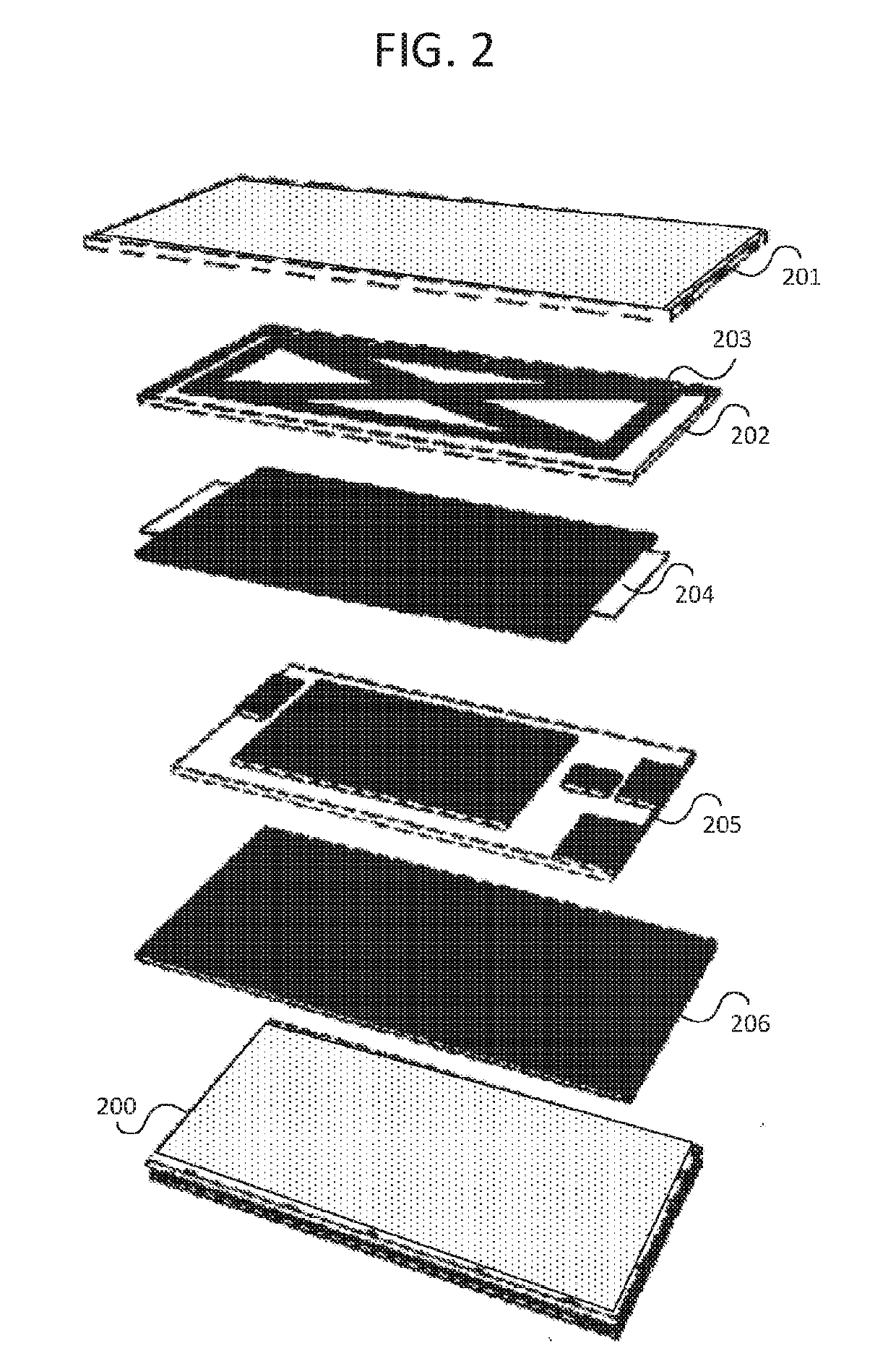
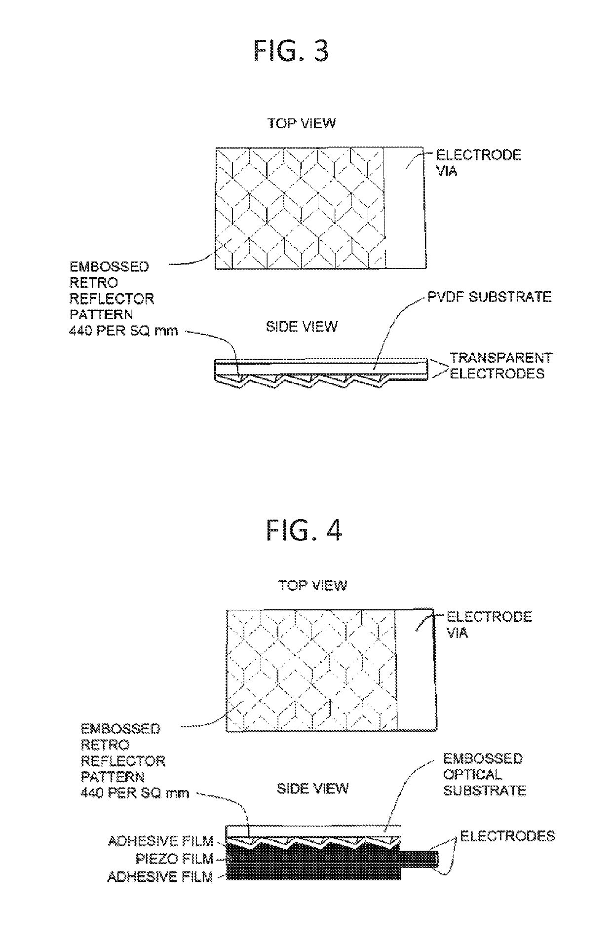
The invention is a modulating retroreflective multilayer film that can be used for various applications such as a label for articles or a miniature spacecraft. The film comprises a piezoelectric layer made of PVDF, and a plurality of retroreflective elements. The film also has first and second electrode layers, an energy storage device, and a photovoltaic layer. The film can store energy and apply voltage across the piezoelectric layer or power to the processor. The label can be easily attached to an article by using the multilayer film. The technical effects of the invention include improved modulation of retroreflected light, efficient energy storage, and improved labeling of articles.

Problems solved by technology

One drawback of this type of retroreflector arrangement is that a relatively large angular displacement is used to cause the retroreflector to reflect or not reflect the incoming beam.
The relatively large angular displacement represents challenges with respect to the device geometry, energy consumed by the device, operation frequency, and other performance criteria.
For example, the modulation bandwidth may be limited by the response time of the tilted reflective surface, the limitation being exacerbated by inherent response time delays of the modulation device, such as may be observed with voltage slew notes.
However, such a device requires two or more reflective surfaces in conjunction with a retroreflector.
Such a configuration can be somewhat complex and have a limited bandwidth due to device response time.
This type of modulated retroreflector can be somewhat expensive and represents other design challenges due to the absorption of energy when the shutter is in a non-transmissive state.
As with other modulated retroreflectors described above, the optical shutter device also can have a limited bandwidth due to device component response times.
However, many tagging devices depend on omni-directional RF signals that can be intercepted or jammed.

Method used


Image

  • Modulating retroreflective piezoelectric multilayer film
  • Modulating retroreflective piezoelectric multilayer film
  • Modulating retroreflective piezoelectric multilayer film

Examples


embodiment 1

[0091] A modulating retroreflective multilayer film comprising: retroreflective elements; a piezoelectric layer having opposing top and bottom surfaces; a first electrode layer in electrical connection with the top surface of the piezoelectric layer; a second electrode layer in electrical connection with the bottom surface of the piezoelectric layer; a voltage source located within a layer of the multilayer film and being in electrical connection with the first and second electrode layers; a processor located within a layer of the multilayer film and being communicably coupled with the voltage source to apply a voltage across the piezoelectric layer; an energy storage device located within a layer of the multilayer film and being configured to store energy used for the applying of the voltage; and a photovoltaic layer communicably in electrical connection with the energy storage device and coupled with the processor to transmit electrical signals to the processor.

embodiment 2

[0092] An embodiment of embodiment 1, wherein the retroreflective elements are disposed on the top surface or the bottom surface of the piezoelectric layer.

embodiment 3

[0093] An embodiment of embodiment 1, further comprising: a retroreflective layer comprising at least some of the retroreflective elements.


PUM


Abstract

Provided herein is a modulating retroreflective multilayer film comprising retroreflective elements, a piezoelectric layer, a photovoltaic layer, and an energy storage device. The stacked and transparent layered configuration of the film allows the retroreflective elements and the photovoltaic layer to be simultaneously illuminated by a narrow beam. The low power piezoelectric layer and the energy harvesting of the photovoltaic layer allow the retroreflector to be energetically self-sufficient and suitable for remote deployment. The flexible properties of the component layers allow the retroreflector to be adhered to nonplanar or irregular surfaces for the purpose of labeling and tagging.

Description

CROSS-REFERENCE TO RELATED APPLICATIONS[0001]The present application claims the benefit of U.S. Provisional Application No. 62 / 380,263 filed Aug. 26, 2016, the full disclosure of which is incorporated herein by reference in its entirety for all purposes.FIELD OF THE INVENTION[0002]The present invention relates generally to modulating retroreflectors, in particular to modulating retroreflectors in the form of a thin multilayer film including a piezoelectric layer, a photovoltaic layer, an energy storage device, and retroreflective elements.BACKGROUND OF THE INVENTION[0003]Conventional retroreflectors are fairly well known. In general, retroreflectors have the property of receiving an incident beam, from a source such as an optical or radio frequency (RF) beam, and directing a retroreflected beam back to the source through one or more reflections. Modulating retroreflectors provide the advantage that the retroflected beam contains information and carries the information back to the so...

Claims


Application Information

Patent Timeline
IPC IPC(8): G02B26/02H01L41/047H01L31/053H01L27/20H01L41/193H01L41/09G09F3/02G09F3/10
CPCG02B26/02H01L41/0478H01L31/053H01L27/20H01L41/193H01L41/0926G09F3/02G09F3/10G09F2003/0257B64G1/1085B64G1/66G01S17/74G06K7/10544H10N39/00H10N30/878H10N30/204H10N30/857Y02E10/50G02B5/124
Inventor FILO, ANDREW SIMON
Owner ANDREW SIMON FILO
Features
  • Generate Ideas
  • Intellectual Property
  • Life Sciences
  • Materials
  • Tech Scout
  • Unparalleled Data Quality
  • Higher Quality Content
  • 60% Fewer Hallucinations
Learn More