Photomasks including shading layer and methods of forming patterns using the same

Active Publication Date: 2019-06-27
SK HYNIX INC
View PDF0 Cites 1 Cited by
  • Summary
  • Abstract
  • Description
  • Claims
  • Application Information

AI Technical Summary

Benefits of technology

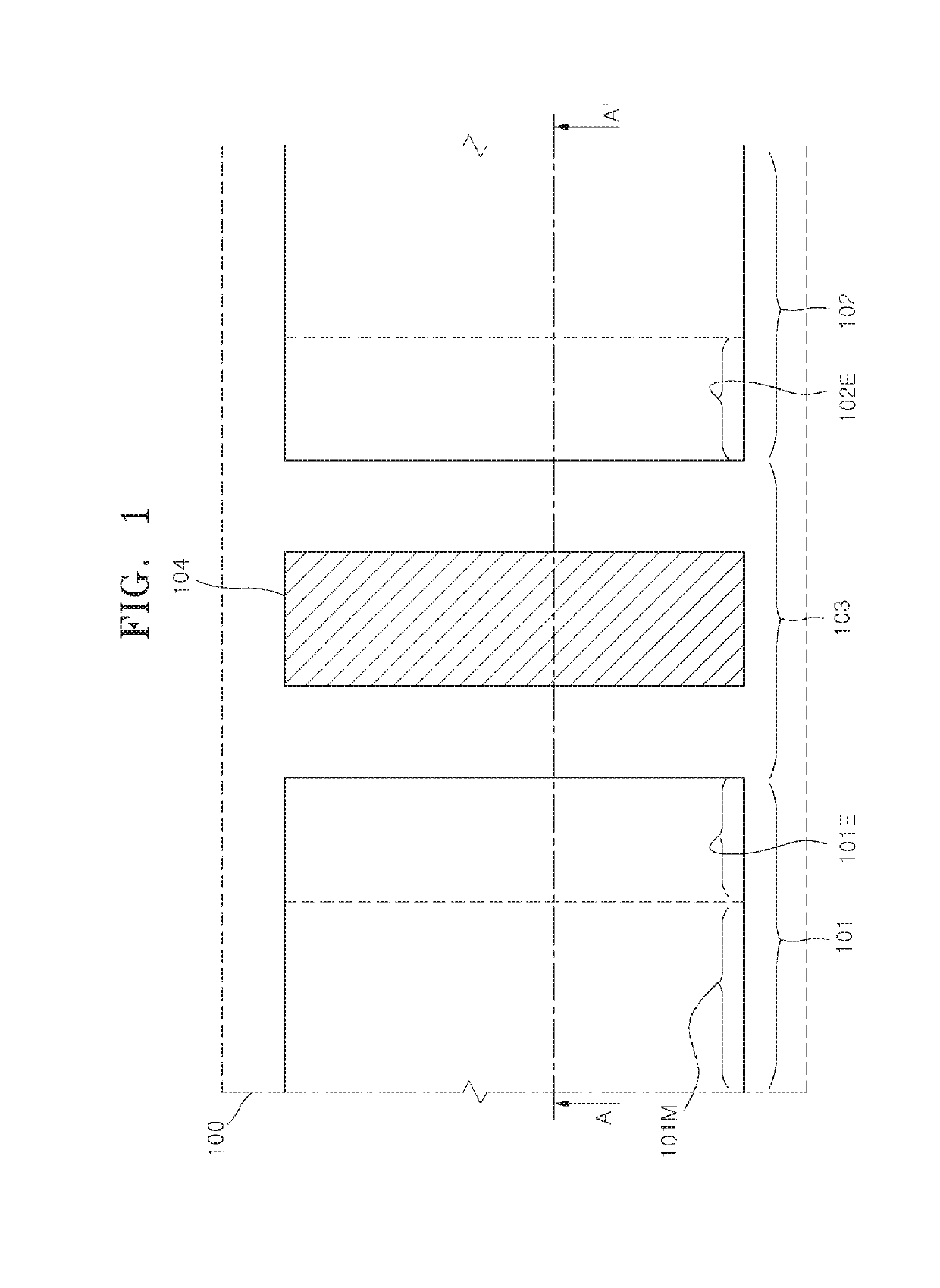
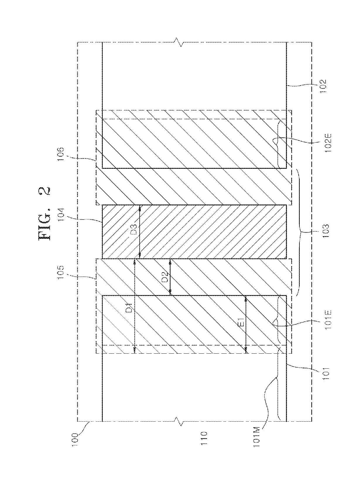
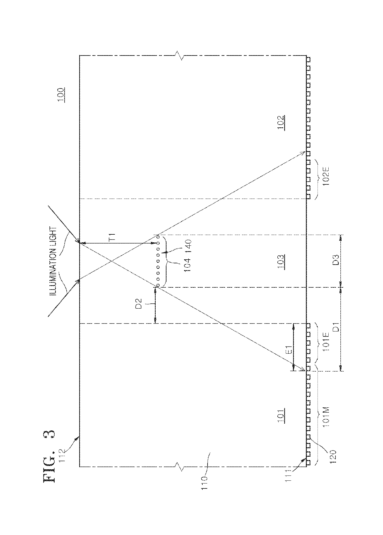
[0006]In accordance with another embodiment, there is provided a method of forming patterns using a photomask including a mask body including a pattern region and a peripheral region and having a first surface and a second surface, mask patterns disposed on a portion overlapping with the pattern region of the first surface of the mask body, and a shading layer disposed in the peripheral region, wherein the shading layer provides a spill-over-shading region extending to overlap with a critical dimension (CD) correction region in which CD correction in the pattern region is required. The method includes changing a position of the shading layer to control a width of an overlap region of the spill-over-shading region and the pattern region. Pattern images are transferred onto a resist lay

Problems solved by technology

Generally, as the size of the fine patterns is reduced, it becomes more difficult to control the critical dimensions (CDs) of the fine patterns.
In such a

Method used


Image

  • Photomasks including shading layer and methods of forming patterns using the same
  • Photomasks including shading layer and methods of forming patterns using the same
  • Photomasks including shading layer and methods of forming patterns using the same

Examples


Example

[0017]Hereinafter, various embodiments will be described in detail with reference to the accompanying drawings to the extent that a person skilled in the art to which the embodiments pertain may easily practice the embodiments. Among the reference numerals presented in the drawings, like reference numerals denote like members.

[0018]In describing the present disclosure, when it is determined that the detailed description of the known related art may obscure the gist of the present disclosure, the detailed description thereof will be omitted.

[0019]The terms used herein may correspond to words selected in consideration of their functions in the embodiments, and the meanings of the terms may be construed to be different according to the meaning that a skilled person having ordinary skill in the art would understand them in view of the described embodiments. If defined in detail, the terms may be construed according to the definitions. Unless otherwise defined, the terms used herein have...


PUM


Abstract

A photomask and a method of forming patterns using the photomask are provided. The photomask includes a mask body including a pattern region and a peripheral region and having a first surface and a second surface. Mask patterns are disposed on a portion overlapping with the pattern region of the first surface of the mask body. A shading layer is disposed in the peripheral region. The shading layer provides a spill-over-shading region extending to overlap with a critical dimension (CD) correction region in which CD correction in the pattern region is required.

Description

CROSS-REFERENCE TO RELATED APPLICATIONS[0001]The present application claims priority under 35 U.S.C 119(a) to Korean Application No. 10-2017-0176686, filed on Dec. 21, 2017, which is incorporated herein by references in its entirety.BACKGROUND1. Technical Field[0002]The present application relates to a lithography technology and, more particularly, to photomasks including a shading layer and methods of forming patterns using the same.2. Related Art[0003]In the semiconductor industry, various techniques for forming fine patterns on a wafer have been used for increasing the integration density of semiconductor devices. Generally, as the size of the fine patterns is reduced, it becomes more difficult to control the critical dimensions (CDs) of the fine patterns. Accordingly, it may be necessary to develop techniques for improving the uniformity of the CDs of the fine patterns.[0004]When fine patterns are formed on a wafer, a lithography technique may be used to transfer images of mask ...

Claims


Application Information

Patent Timeline
IPC IPC(8): G03F1/36
CPCG03F1/36G03F1/38G03F7/2047G03F7/70141G03F7/70058G03F7/70691
Inventor JEONG, SOO KYEONG
Owner SK HYNIX INC
Why Eureka
Try Eureka