Flow fluorometric method

a flow cytometry and flow method technology, applied in the direction of material testing goods, instruments, analysis by subjecting materials to chemical reactions, etc., can solve the problems of high-sensitivity flow cytometry, sensitivity of detection substantially limited, and high cost of argon-ion lasers, etc., to achieve better signal-to-noise conditions

Inactive Publication Date: 2001-01-23
SOINI ERKKI
View PDF20 Cites 161 Cited by
  • Summary
  • Abstract
  • Description
  • Claims
  • Application Information

AI Technical Summary

Benefits of technology

Another method for size determination is based on the use of a method called "Flying Light Scattering Indicatrix" (later "FLSI") which means determination of the angular dependency of the intensity of light scattered by a moving individual particle i.e. the light scattering pattern (V. P. Maltsev, "Estimation of morphological characteristics of single particles from light scattering data in flow cytometry," Russian Chemical Bulletin 43, 1115-1124 (1994)). The FLSI method employs a special optical scanning system which provides measurement of the intensity of the light scattered at polar

Problems solved by technology

However, the sensitivity of detection is substantially limited by the illumination light scattering, background fluorescence of the optical parts

Method used


Image

  • Flow fluorometric method

Examples


Embodiment Construction

and Performance of a Confocal Set-Up

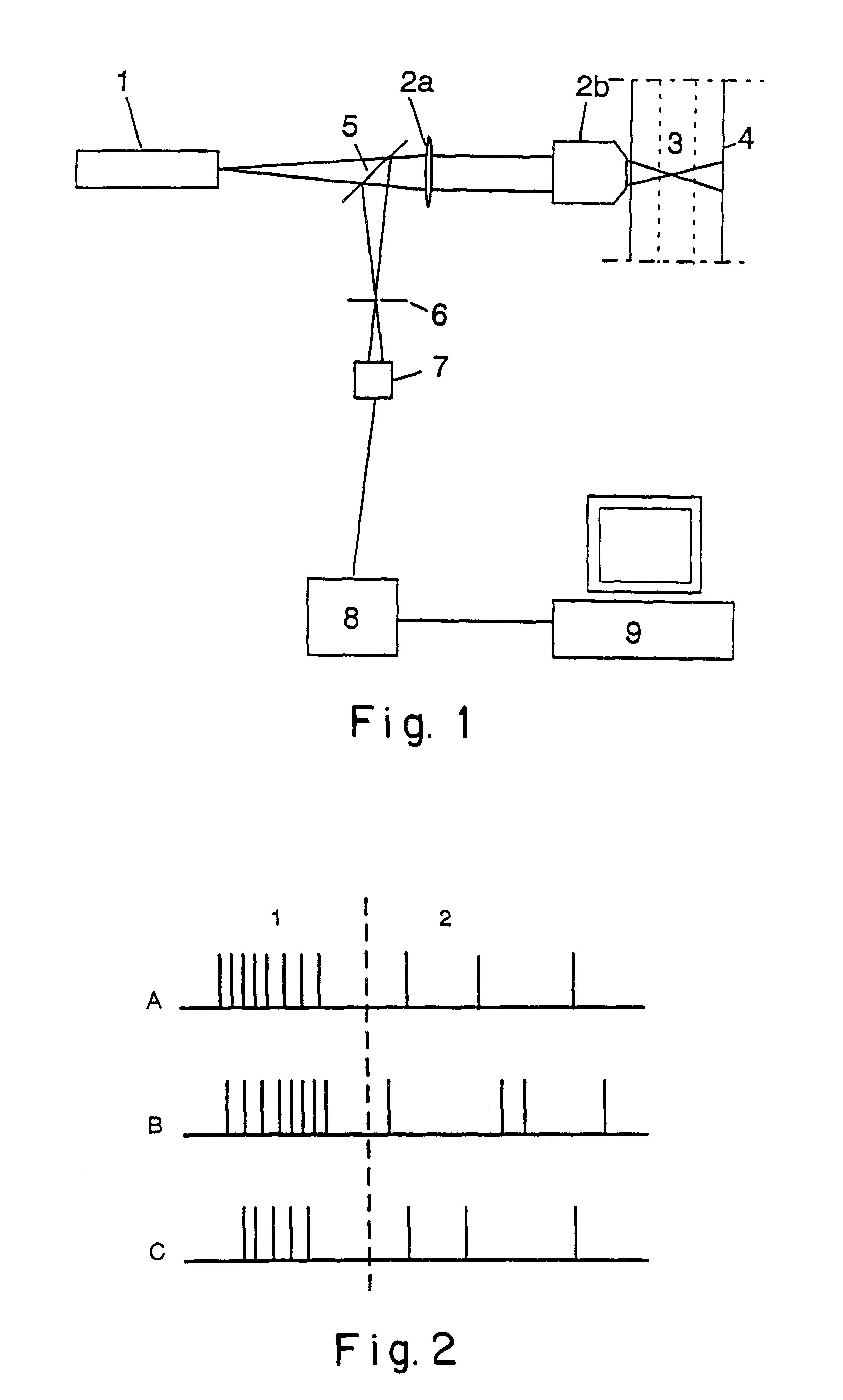
The optical set-up and its performance as shown in FIG. 1 was tested. The light source (1) was a frequency doubled 10 mW CW Nd:YAG laser producing 300 .mu.W beam at 532 nm wavelength. The illumination light was focused to the sample (3) through a microscope objective (2b) with numerical aperture of 0.5. The sample (3) was fed through a position-adjustable capillary tube (4) in conjunction with a simple liquid handling system. The emitted fluorescence light was separated from the illumination light by a dichroic mirror (5) and pinhole / aperture (6), and was detected by an avalanche photon counter (7)(EG&G Optoelectronics, Canada, type SPCM-141-AQ).

The set-up was tested in single-photon excitation confocal fluorescence mode with a test-sample containing E.coli bacteria stained with specific Rhodamine-B labelled antibodies at a predetermined concentration. The single photon bursts detected from the bacteria were Poisson distributed in the time domain ...


PUM


Abstract

This invention is related to a flow fluorometric device and method employing a two-photon excitation and/or confocal optical set-up. The optical set-up of this invention is optimal for counting small fluorescent biological particles. The active focal volume is diffraction-limited and consequently much smaller than the volume of the flow channel. The excitation and detection concept has been found very efficient for rejection of the background signal. An objective lens with large numerical aperture for focusing the laser and for collecting the fluorescence is used and this restricts the active volume of measurement to a diffraction-limited volume which approximately corresponds to a volume of femtoliter. This volume is significantly smaller than the detection volume of ordinary flow cytometry.

Description

A flow cytometer is a device which is now widely used in routine diagnostics and research laboratories for analyzing and classifying cells and other particles. The cells are in liquid suspension and this suspension is pumped through a thin capillary cuvette and a laser beam is focused to the stream at a 90.degree. angle in relation to the laser beam and detection objective lens. The laser beam can also be focused on the stream outside the capillary orifice. The sample suspension is kept in the focus of the laser beam using hydrodynamic focusing which forces the cells to flow along the centre of the axis of the capillary cuvette. Flow cytometry has recently been reviewed in many articles and e.g. by Salzman & al. in: Flow Cytometry and Sorting, Second Edition, M. R. Melamed, T. Lindmo, M. L. Mendelsohn, Eds. Wiley & Sons, Inc., New York, 1990, pp. 81-107.The cells are normally stained with one or several fluorescent dyes or fluorescent biomolecules e.g. antibodies and flow cytometers...

Claims


Application Information

Patent Timeline
IPC IPC(8): G01N15/14G01N21/64G01N33/49
CPCG01N15/1434G01N15/1459
Inventor SOINI, ERKKI
Owner SOINI ERKKI
Why Eureka
Try Eureka