System for detection of spaced droplets

a technology of spaced droplets and detection systems, applied in the field of system for detection of spaced droplets, can solve the problems of increasing cost, increasing instrumentation complexity, and emulsion-based assays presenting technical challenges for high-throughput testing

Active Publication Date: 2011-12-22
LAWRENCE LIVERMORE NAT SECURITY LLC
View PDF5 Cites 157 Cited by
  • Summary
  • Abstract
  • Description
  • Claims
  • Application Information

AI Technical Summary

Benefits of technology

[0003]Many biomedical applications rely on high-throughput assays of samples combined with reagents. For example, in research and clinical applications, high-throughput genetic tests using target-specific reagents can provide high-quality information about samples for drug discovery, biomarker discovery, and clinical diagnostics, among others. As another example, infectious disease detection often requires screening a sample for multiple genetic targets to generate high-confidence results.
[0004]The trend is toward reduced volumes and detection of more targets. However, creating and mixing smaller volumes can require more complex instrumentation, which increases cost. Accordingly, improved technology is needed to permit testing greater numbers of samples and combinations of samples and reagents, at a higher speed, a lower cost, and / or with reduced instrument complexity.
[0006]Splitting a sample into droplets offers numerous advantages. Small reaction volumes (picoliters to nanoliters) can be utilized, allowing earlier detection by increasing reaction rates and forming more concentrated products. Also, a much greater number of independent measurements (thousands to millions) can be made on the sample, when compared to conventional bulk volume reactions performed on a microliter scale. Thus, the sample can be analyzed more accurately (i.e., more repetitions of the same test) and in greater depth (i.e., a greater number of different tests). In addition, small reaction volumes use less reagent, thereby lowering the cost per test of consumables. Furthermore, microfluidic technology can provide control over processes used for the generation, mixing, incubation, splitting, sorting, and detection of droplets, to attain repeatable droplet-based measurements.
[0007]Aqueous droplets can be suspended in oil to create a water-in-oil emulsion (W / O). The emulsion can be stabilized with a surfactant to reduce or prevent coalescence of droplets during heating, cooling, and transport, thereby enabling thermal cycling to be performed. Accordingly, emulsions have been used to perform single-copy amplification of nuclei acid target molecules in droplets using the polymerase chain reaction (PCR).
[0008]Compartmentalization of single molecules of a nucleic acid target in droplets of an emulsion alleviates problems encountered in amplification of larger sample volumes. In particular, droplets can promote more efficient and uniform amplification of targets from samples containing complex heterogeneous nucleic acid populations, because sample complexity in each droplet is reduced. The impact of factors that lead to biasing in bulk amplification, such as amplification efficiency, G+C content, and amplicon annealing, can be minimized by droplet compartmentalization. Unbiased amplification can be critical in detection of rare species, such as pathogens or cancer cells, the presence of which could be masked by a high concentration of background species in complex clinical samples.

Problems solved by technology

However, creating and mixing smaller volumes can require more complex instrumentation, which increases cost.
Despite their allure, emulsion-based assays present technical challenges for high-throughput testing.
However, detection of signals from closely packed droplets may be problematic because the signals cannot always be correctly assigned to individual droplets.

Method used


Image

  • System for detection of spaced droplets
  • System for detection of spaced droplets
  • System for detection of spaced droplets

Examples


example 1

Detection System 1

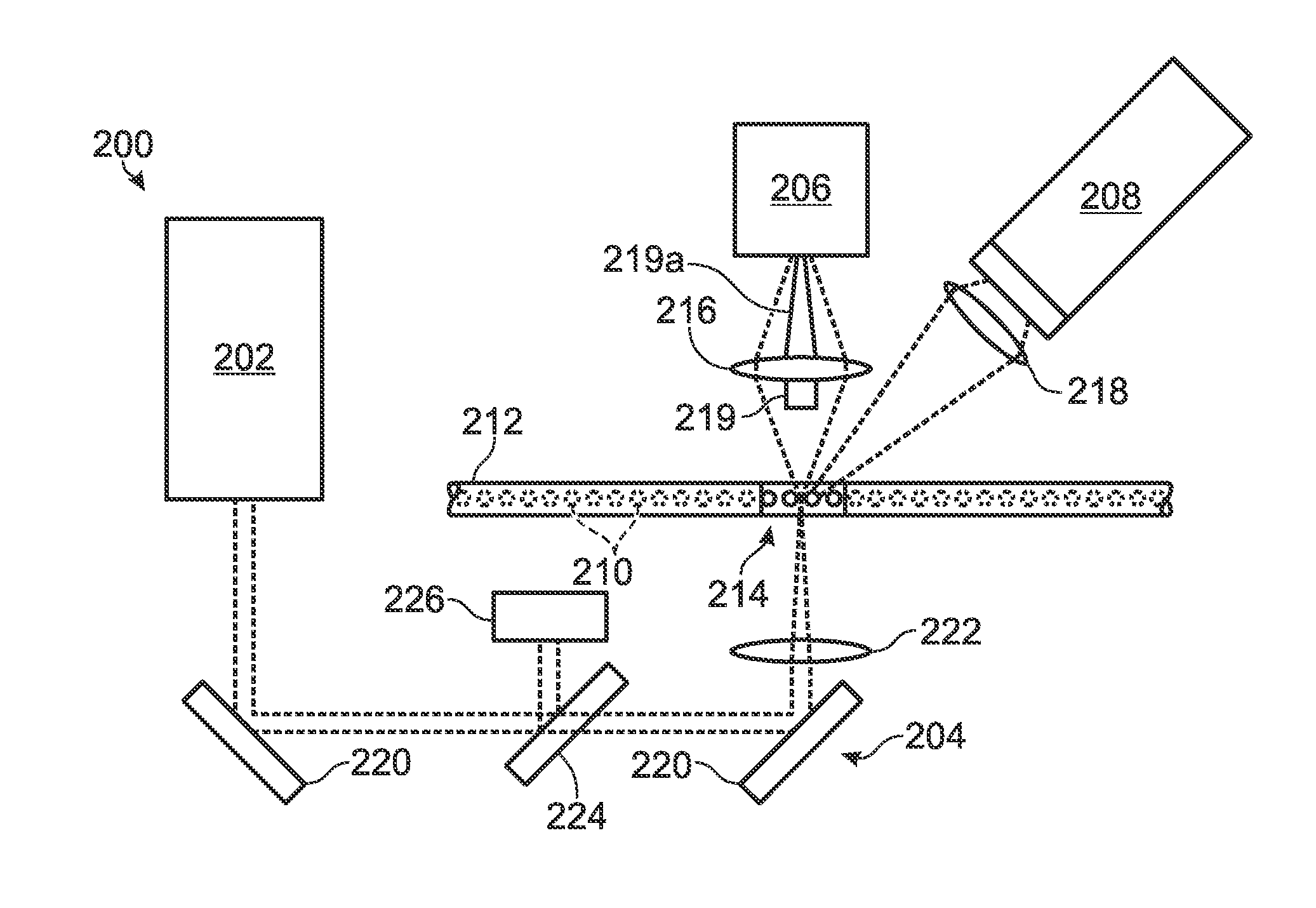
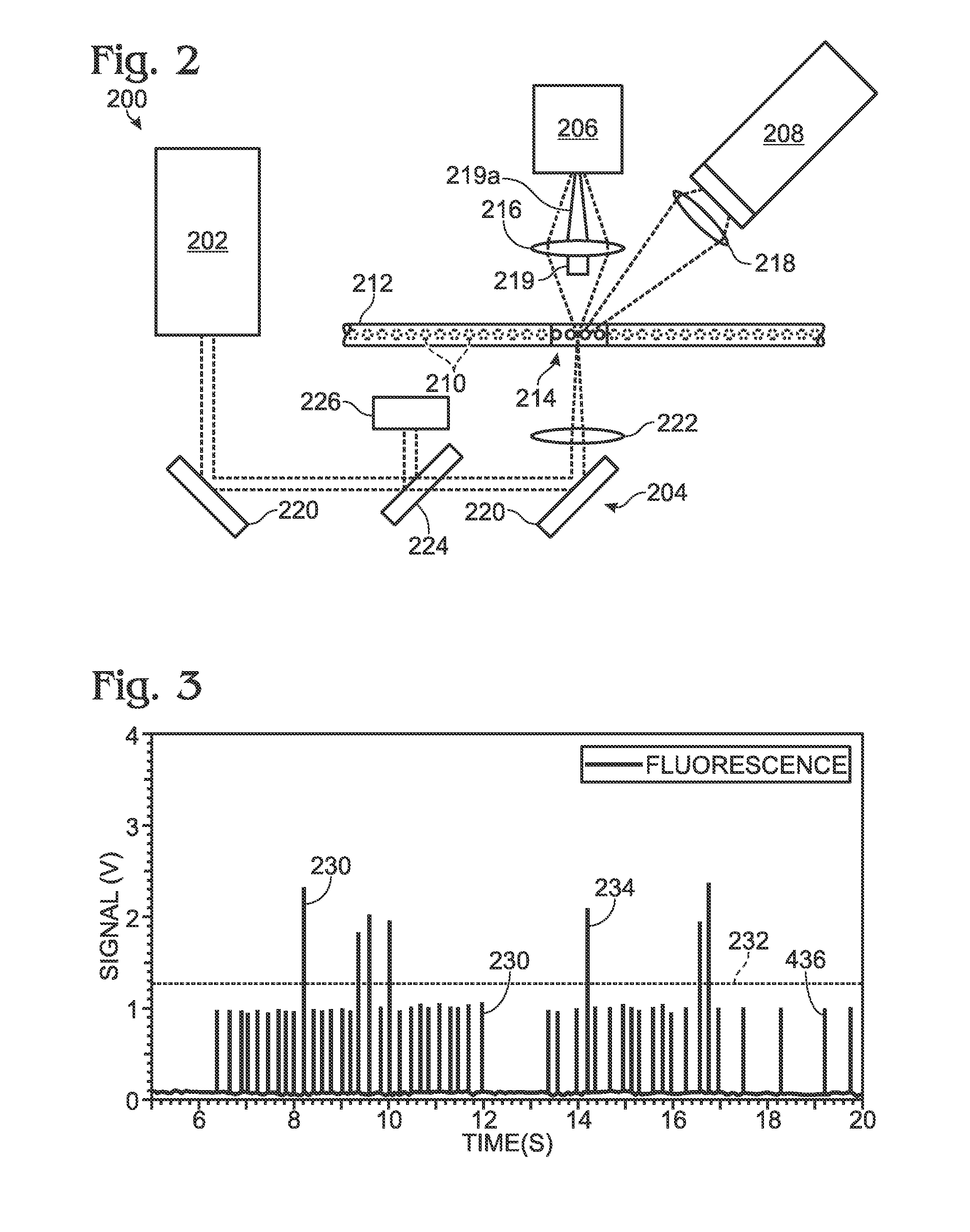
[0054]This example describes an optical detection system based on measuring the end-point fluorescence signal of each sample / reagent droplet after a PCR amplification process is complete. The exemplary system is suitable for making both qualitative and quantitative measurements; see FIGS. 2 and 3.

[0055]FIG. 2 depicts a detection system 200 configured to detect both scattered and fluorescence radiation. Detection system 200 includes a radiation source 202, transmission optics generally indicated at 204, a forward scatter detector 206, and a fluorescence detector 208. The forward scatter detector may be replaced or augmented, in some embodiments, by side and / or back scatter detectors, among others, configured to detect light detected to the side or back of the sample, respectively. Similarly, the fluorescence detector may be replaced or augmented, in some embodiments, by an epi-fluorescence detector, among others, configured to detect fluorescence emitted anti-parall...

example 2

Detection Systems Using Optical Fibers

[0068]This example describes fluorescence detectors configured to measure the end-point fluorescence signal of sample / reagent droplet after PCR, and which utilize one or more optical fibers to transmit radiation to and / or from an intersection region within which illuminating radiation intersects the path of the sample-containing droplets. The exemplary systems are suitable for making both qualitative and quantitative measurements; see FIGS. 4-9.

[0069]FIG. 4 depicts an optical detection system, generally indicated at 250, which is similar to system 200 depicted in FIG. 2 except that transmission optics 204 of system 200 have been replaced by an optical fiber 254. Optical fiber 254 may be constructed from a glass, a plastic, and / or any other material that is substantially transparent to radiation of one or more particular desired wavelengths and configured to transmit that radiation along the length of the fiber, preferably with little or no loss ...

example 3

Detection Systems with Plural Radiation Channels

[0086]In some cases, a detection system according to the present disclosure may include multiple separate incident radiation channels to illuminate sample-containing droplets that have undergone PCR thermocycling. This example describes two such systems and some of their potential uses; see FIGS. 10 and 11.

[0087]FIG. 10 depicts a multi-channel cytometry-type optical detection system, generally indicated at 400. Detection system 400 includes a radiation source 402, configured to emit radiation at one or more desired wavelengths. As described previously, a radiation source according to the present disclosure may be of various types, such as an LED source or a laser source, and may emit radiation substantially at a single wavelength, at a plurality of substantially discrete wavelengths, or within one or more ranges of wavelengths.

[0088]Radiation from source 402 passes from the source toward transmission optics, as generally indicated at 4...


PUM

PropertyMeasurementUnit
wavelengthaaaaaaaaaa
diameteraaaaaaaaaa
diameteraaaaaaaaaa

Abstract

System, including methods and apparatus, for detection of spaced droplets.

Description

CROSS-REFERENCES TO PRIORITY APPLICATIONS[0001]This application is based upon and claims the benefit under 35 U.S.C. §119(e) of U.S. Provisional Patent Application Ser. No. 61 / 317,635, filed Mar. 25, 2010, and U.S. Provisional Patent Application Ser. No. 61 / 467,347, filed Mar. 24, 2011, and is a continuation-in-part of U.S. patent application Ser. No. 12 / 586,626, filed Sep. 23, 2009, Pub. No. US-2010-0173394-A1, which in turn is based upon and claims the benefit under 35 U.S.C. §119(e) of the following U.S. provisional patent applications: Ser. No. 61 / 194,043, filed Sep. 23, 2008; Ser. No. 61 / 206,975, filed Feb. 5, 2009; Ser. No. 61 / 271,538, filed Jul. 21, 2009; Ser. No. 61 / 275,731, filed Sep. 1, 2009; Ser. No. 61 / 277,200, filed Sep. 21, 2009; Ser. No. 61 / 277,203, filed Sep. 21, 2009; Ser. No. 61 / 277,204, filed Sep. 21, 2009; Ser. No. 61 / 277,216, filed Sep. 21, 2009; Ser. No. 61 / 277,249, filed Sep. 21, 2009; and Ser. No. 61 / 277,270, filed Sep. 22, 2009. These priority applications a...

Claims


Application Information

Patent Timeline
Patent Type & Authority Applications(United States)
IPC IPC(8): C12Q1/68C12M1/34
CPCB01F3/0807G01N21/645B01L3/0241B01L3/502715B01L3/502784B01L3/563B01L7/52B01L7/525B01L2200/0689B01L2300/0816B01L2300/0819B01L2300/1822B01L2400/0478B01L2400/0487B01L2400/0622B01F13/0062B01F23/41B01F33/3011
Inventor MAKAREWICZ, JR., ANTHONY J.HIDDESSEN, AMY L.
Owner LAWRENCE LIVERMORE NAT SECURITY LLC
Why Eureka
Try Eureka