Droplet transport system for detection

a technology of droplet transport and detection system, which is applied in the direction of fluid controller, biochemistry apparatus and processes, laboratory glassware, etc., can solve the problems of emulsion-based assays and technical challenges for high-throughput testing

Active Publication Date: 2016-07-19
BIO RAD LAB INC
View PDF353 Cites 10 Cited by
  • Summary
  • Abstract
  • Description
  • Claims
  • Application Information

AI Technical Summary

Benefits of technology

[0003]Many biomedical applications rely on high-throughput assays of samples. For example, in research and clinical applications, high-throughput genetic tests using target-specific reagents can provide high-quality information about samples for drug discovery, biomarker discovery, and clinical diagnostics, among others. As another example, infectious disease detection often requires screening a sample for multiple genetic targets to generate high-confidence results.

Problems solved by technology

Despite their allure, emulsion-based assays present technical challenges for high-throughput testing.

Method used


Image

  • Droplet transport system for detection
  • Droplet transport system for detection
  • Droplet transport system for detection

Examples


example 1

Exemplary Transport Systems with a Two-State Multi-port Valve

[0051]This example describes exemplary droplet transport systems with a two-state (i.e., two-configuration) multi-port valve to permit switching between two sets of channel connections utilized by three pumps; see FIGS. 3 and 4.

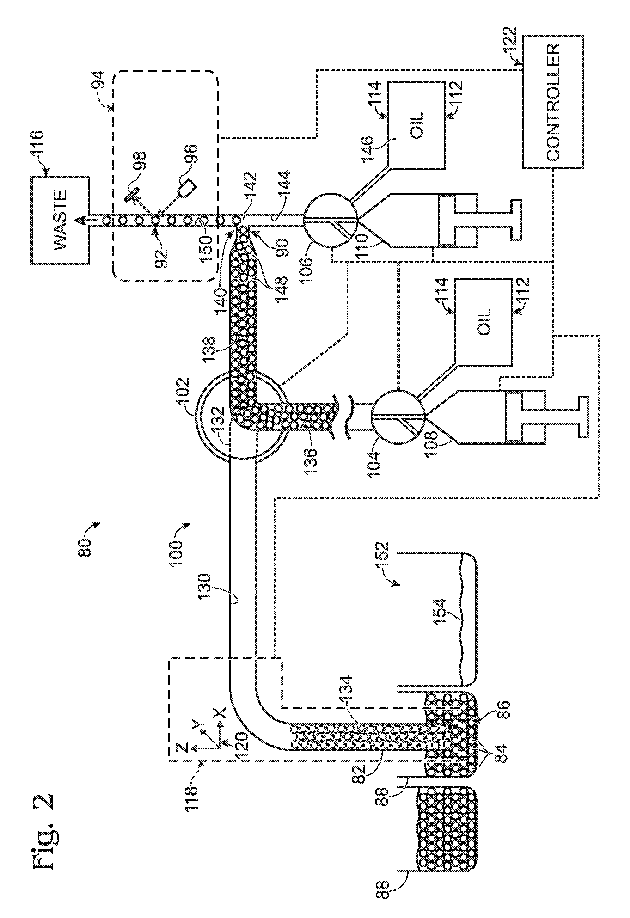
[0052]FIG. 3 shows an exemplary embodiment 170 of droplet transport system 80 of FIG. 2. Transport system 170 may include any combination of the components and features disclosed herein for other transport systems.

[0053]Transport system 170 operates generally as described above for transport system 80, with counterpart elements of system 170 functioning similarly, except where noted below, and being assigned the same reference numbers as those of system 80.

[0054]Emulsions may be held by a multi-well plate 172, which provides containers 88 (i.e., wells) for individual emulsions 86. The droplets of each emulsion may, for example, be thermally cycled as a batch before loading them into transport system...

example 2

Exemplary Transport System with a Coaxial Tip

[0068]This example describes an exemplary droplet transport system with a coaxial tip; see FIGS. 5-9.

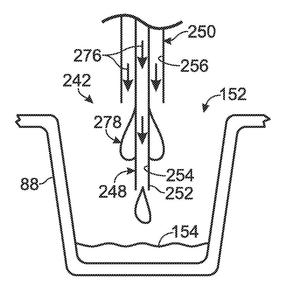
[0069]FIG. 5 shows an exemplary embodiment 240 of droplet transport system 80 of FIG. 2. Transport system 240 may include any combination of the components and features disclosed herein for other transport systems. Transport system 240 operates generally as described above for transport systems 80 and 170, with counterpart elements functioning similarly, except where noted below, and being assigned the same reference numbers. However, system 240 may incorporate a number of new components and features as described below, such as a coaxial tip 242.

[0070]FIG. 6 shows a fluidic assembly 244 including tip 242, with the assembly supported by an arm 246 of drive assembly 118. Tip 242 may include an inner tube 248 and an outer tube 250 arranged coaxially. Inner tube 248 may project from the lower end of outer tube 250 to form a nose 252. Nose may ...

example 3

Exemplary Procedures for Using Droplet Transport Systems

[0084]This example describes exemplary procedures and other considerations for using droplet transport systems, such as the system of Example 2, among others. These procedures may include the following classes of operations: (A) pre-plate processing, (B) well processing, (C) post-plate processing, and (D) special operations.

[0085]A. Pre-Plate Processing

[0086]Before the first well (or container) is processed, the following operations may be executed:

[0087]Detector Start.

[0088]The performance of the detector may be sensitive to temperature. For example, the color spectra of the detector LEDs may change with temperature. The LEDs emit heat during use and may require a warm-up period to achieve a stable operating temperature. The LEDs can be turned on in advance of well processing to assure that the temperature and color spectra are stable before processing wells.

[0089]Pump Initialization.

[0090]Since the system can be in an unknown...


PUM

PropertyMeasurementUnit
internal diameteraaaaaaaaaa
lengthaaaaaaaaaa

Abstract

Method of transporting droplets for detection. An emulsion disposed in a container and including droplets may be provided. Contact may be created between a tip and the emulsion. The tip may be connected to an examination region and may include an outer tube and an inner tube. The outer tube may form a first open end and surround an enclosed portion of the inner tube. The inner tube may extend out of the first open end to create a projecting portion forming a second open end below the first open end. Droplets of the emulsion may be loaded into the inner tube via the second open end. Loaded droplets may be moved from the inner tube to the examination region. Fluid may be dispensed onto the projecting portion of the inner tube from the first open end formed by the outer tube.

Description

CROSS-REFERENCES TO PRIORITY APPLICATIONS[0001]This application is a continuation of PCT Patent Application Serial No. PCT / US2011 / 030077, filed Mar. 25, 2011, which, in turn, claims the benefit under 35 U.S.C. §119(e) of the following U.S. provisional patent applications: Ser. No. 61 / 341,065, filed Mar. 25, 2010; and Ser. No. 61 / 467,347, filed Mar. 24, 2011. Each of these priority applications is incorporated herein by reference in its entirety for all purposes.CROSS-REFERENCES TO OTHER MATERIALS[0002]This application incorporates by reference in its entirety for all purposes each of the following materials: U.S. Pat. No. 7,041,481, issued May 9, 2006; U.S. Patent Application Publication No. 2010 / 0173394 A1, published Jul. 8, 2010; and Joseph R. Lakowicz, PRINCIPLES OF FLUORESCENCE SPECTROSCOPY (2nd Ed. 1999).INTRODUCTION[0003]Many biomedical applications rely on high-throughput assays of samples. For example, in research and clinical applications, high-throughput genetic tests usin...

Claims


Application Information

Patent Timeline
Patent Type & Authority Patents(United States)
IPC IPC(8): B01L3/02
CPCB01L3/021B01L2200/0673B01L2400/0478B01L2400/0622
Inventor NESS, KEVIN D.HINDSON, BENJAMIN J.MAKAREWICZ, JR., ANTHONY J.HIDDESSEN, AMY L.
Owner BIO RAD LAB INC
Why Eureka
Try Eureka