Microfluidic system with fluid pickups

a microfluidic system and fluid pickup technology, applied in fluid controllers, biochemical apparatus and processes, laboratory glassware, etc., can solve the problems of increasing cost, emulsion-based assays present technical challenges for high-throughput testing, and more complex instruments

Active Publication Date: 2016-08-09
BIO RAD LAB INC
View PDF14 Cites 18 Cited by
  • Summary
  • Abstract
  • Description
  • Claims
  • Application Information

AI Technical Summary

Benefits of technology

[0003]Many biomedical applications rely on high-throughput assays of samples combined with reagents. For example, in research and clinical applications, high-throughput genetic tests using target-specific reagents can provide high-quality information about samples for drug discovery, biomarker discovery, and clinical diagnostics, among others. As another example, infectious disease detection often requires screening a sample for multiple genetic targets to generate high-confidence results.
[0004]The trend is toward reduced volumes and detection of more targets. However, creating and mixing smaller volumes can require more complex instrumentation, which increases cost. Accordingly, improved technology is needed to permit testing greater numbers of samples and combinations of samples and reagents, at a higher speed, a lower cost, and / or with reduced instrument complexity.
[0006]Splitting a sample into droplets offers numerous advantages. Small reaction volumes (e.g., picoliters to nanoliters) can be utilized, allowing earlier detection by increasing reaction rates and forming more concentrated products. Also, a much greater number of independent measurements (e.g., thousands to millions) can be made on the sample, when compared to conventional bulk volume reactions performed on a microliter scale. Thus, the sample can be analyzed more accurately (i.e., more repetitions of the same test) and in greater depth (i.e., a greater number of different tests). In addition, small reaction volumes use less reagent, thereby lowering the cost per test of consumables. Furthermore, microfluidic technology can provide control over processes used for the generation, mixing, incubation, splitting, sorting, and detection of droplets, to attain repeatable droplet-based measurements.
[0007]Aqueous droplets can be suspended in oil to create a water-in-oil emulsion (W / O). The emulsion can be stabilized with a surfactant to reduce or prevent coalescence of droplets during heating, cooling, and transport, thereby enabling thermal cycling to be performed. Accordingly, emulsions have been used to perform single-copy amplification of nucleic acid target sequences in droplets using the polymerase chain reaction (PCR).
[0008]Compartmentalization of single copies of a nucleic acid target in droplets of an emulsion alleviates problems encountered in amplification of larger sample volumes. In particular, droplets can promote more efficient and uniform amplification of targets from samples containing complex heterogeneous nucleic acid populations, because sample complexity in each droplet is reduced. The impact of factors that lead to biasing in bulk amplification, such as amplification efficiency, G+C content, and amplicon annealing, can be minimized by droplet compartmentalization. Unbiased amplification can be critical in detection of rare species, such as pathogens or cancer cells, the presence of which could be masked by a high concentration of background species in complex clinical samples.

Problems solved by technology

However, creating and mixing smaller volumes can require more complex instrumentation, which increases cost.
Despite their allure, emulsion-based assays present technical challenges for high-throughput testing, which can require creation of tens, hundreds, thousands, or even millions of individual samples and sample / reagent combinations.
Droplet generation, in particular, poses a special challenge.
In the past, this has been done primarily by introducing air traps in the sample line, which can require several minutes of delay in wicking of the aqueous sample.
It also has been done by introducing valves into the microfluidic lines, which complicates both fabrication and ease of operation.
Moreover, current droplet generators bubble air through the generated droplets after sample processing has been completed, a phenomenon that is known to damage droplets.

Method used


Image

  • Microfluidic system with fluid pickups
  • Microfluidic system with fluid pickups
  • Microfluidic system with fluid pickups

Examples


example 1

Droplet Generation Device with Fluid Pickups for Sample and Carrier

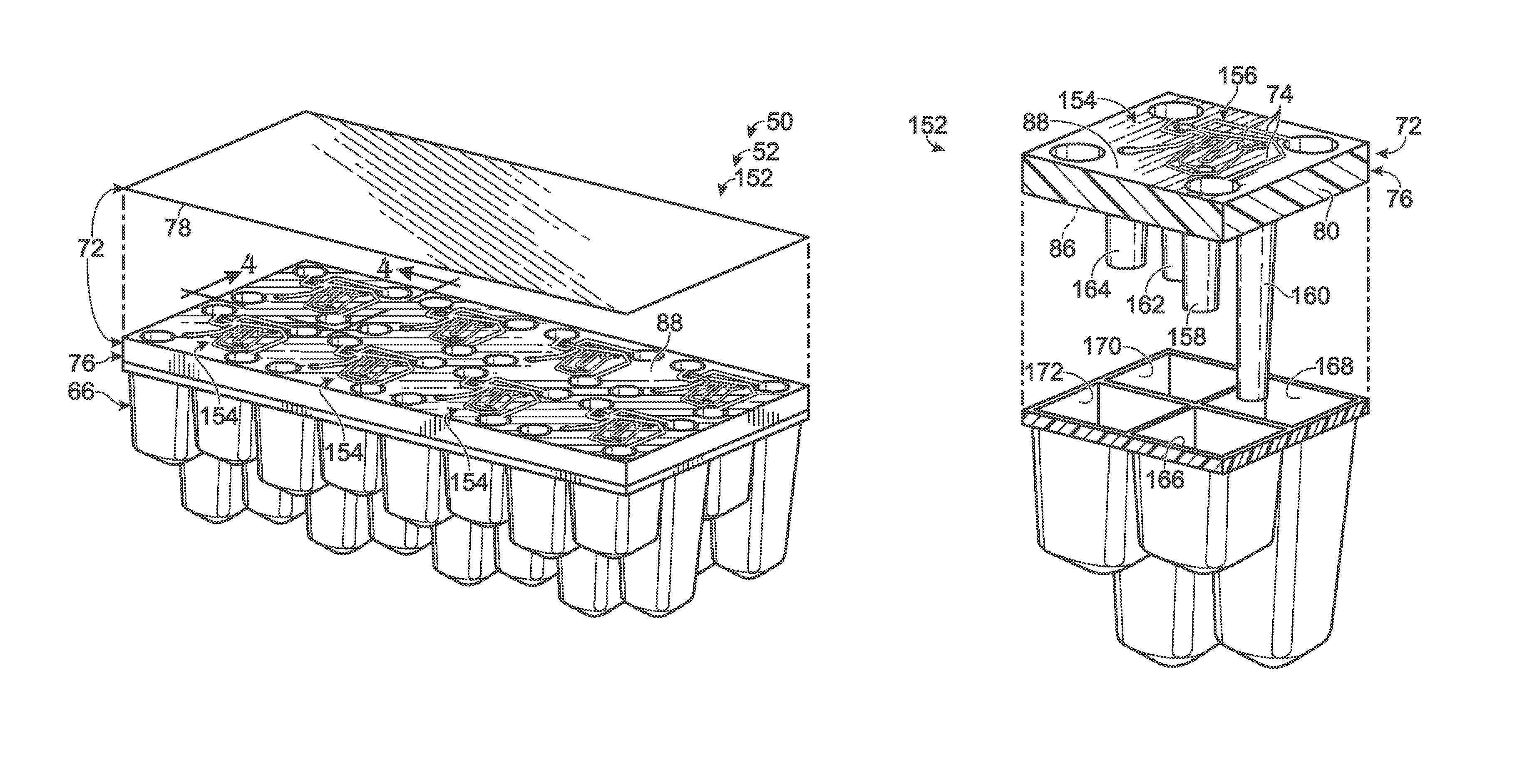
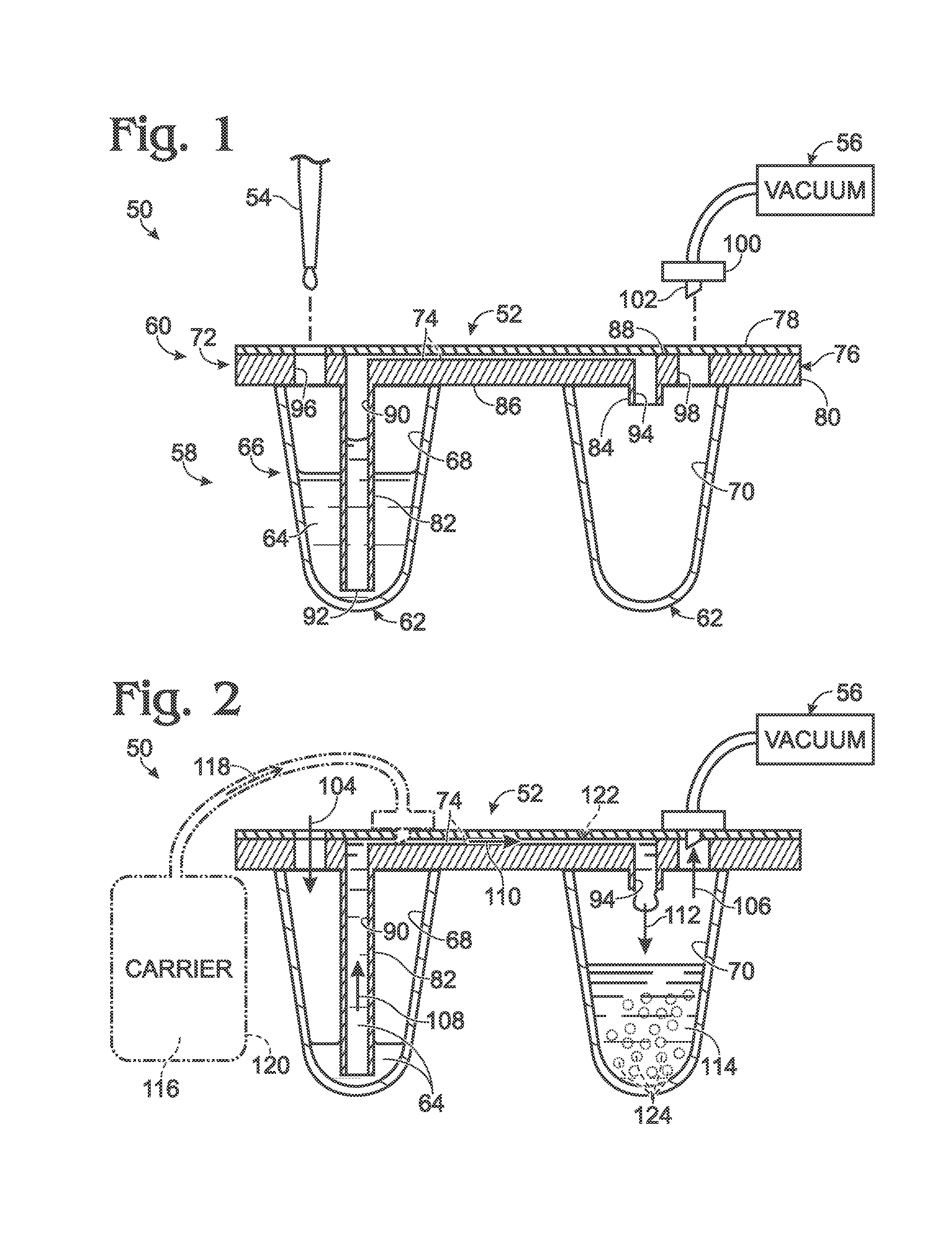
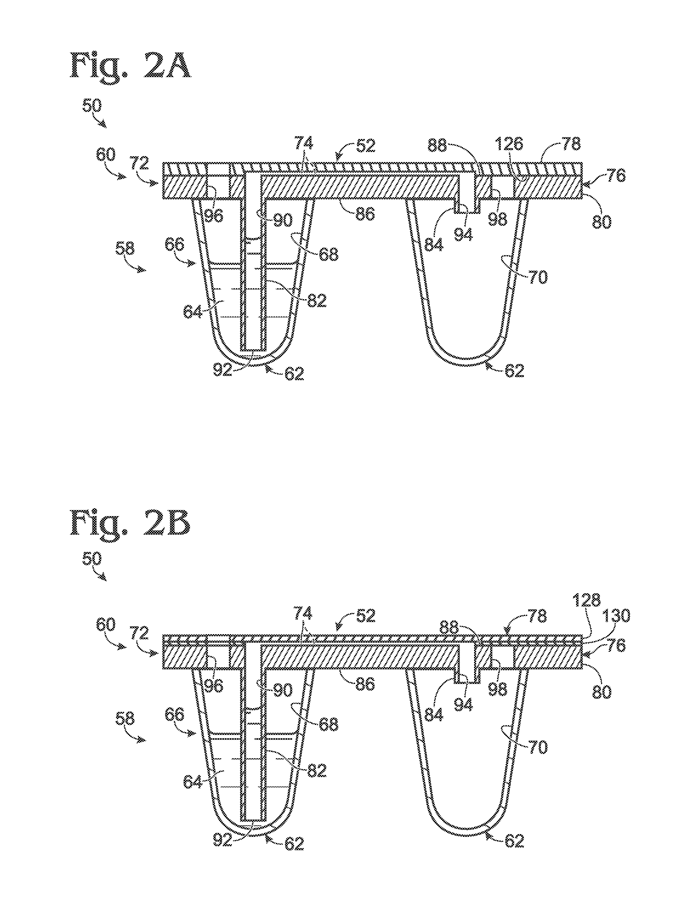
[0075]This example describes an exemplary embodiment 152 of microfluidic device 52 for fluid processing system 50 (see FIGS. 1, 2, 2A, and 2B) that is configured for generating an array of emulsions, and also describes exemplary methods of using device 152 to generate and process emulsions; see FIGS. 3-9. The emulsions are generated with samples and carrier fluid transported from wells to channels via fixed, dedicated pickup tubes.

[0076]Device 152 uses hollow protrusions or “fluid pickups” in conjunction with droplet generators, and provides specific examples of droplet generators in which sample-containing droplets suspended in a carrier fluid are generated and transported substantially within a plane.

[0077]As used herein, “substantially within a plane” or “substantially planar” with respect to droplet generation means that the radius of curvature of the space in which droplets are generated and transported is much ...

example 2

Droplet Generation Device with Fluid Pickups and a Carrier Manifold

[0119]This example describes an exemplary embodiment 252 of microfluidic device 52 for fluid processing system 50 (see FIGS. 1, 2, 2A, and 2B). Device 252 is configured for generating an array of emulsions using a fixed, dedicated pickup tube for the sample of each emulsion. The device also has a carrier manifold that receives carrier fluid for all of the emulsions from an off-device (external) carrier reservoir that is fluidically connected to device 252; see FIGS. 10-18.

[0120]FIGS. 10 and 11 show respective assembled and exploded views of device 252. The device may have any combination of the features described above in Section I and / or Example 1. For example, as described above for device 152, device 252 includes a sample-holding portion, namely, a well component 66 defining a plurality of wells. The device also includes a fluid-processing portion, namely, a channel component 72 attached to the well component and ...

example 3

Exemplary Instrument to Interface with a Microfluidic Device

[0135]This example describes an exemplary instrument 310 configured to fluidically connect to microfluidic device 252 and exemplary methods of using the instrument to generate emulsions; see FIGS. 19-21.

[0136]FIGS. 19 and 20 show instrument 310 of microfluidic system 50 for driving and controlling fluid flow within device 252. Instrument 310 may be configured for use with any of the microfluidic devices disclosed herein. Any or all of the operations performed automatically by instrument 310 alternatively may be performed manually by a user.

[0137]Instrument 310 may include a support 312 to hold and position device 252 with respect to at least one processing head 314. Processing head 314 is positioned or positionable over device 252, in alignment with the device, and is configured to interface with the top side of device 252. In the configuration depicted in FIG. 19, the processing head is in a pre-processing, ready position ...


PUM

PropertyMeasurementUnit
diameteraaaaaaaaaa
heightaaaaaaaaaa
heightaaaaaaaaaa

Abstract

Microfluidic system, including methods and apparatus, for processing fluid, such as by droplet generation. In some embodiments, the system may include a well and a channel component attached to the well. The channel component may include (a) a body, (b) an input tube (a “fluid pickup”) projecting from a bottom surface of the body and having an open bottom end disposed in the input well, (c) a microchannel, and (d) a passage extending through the input tube and the body and connecting the well to the microchannel. The system may be configured to receive a sample-containing fluid in the well and retain the sample-containing fluid below a top end of the passage, until a pressure differential is created that drives at least a portion of the sample-containing fluid from the well via the passage and through the microchannel.

Description

CROSS-REFERENCE TO PRIORITY APPLICATION[0001]This application is based upon and claims the benefit under 35 U.S.C. §119(e) of U.S. Provisional Patent Application Ser. No. 61 / 838,063, filed Jun. 21, 2013, which is incorporated herein by reference in its entirety for all purposes.CROSS-REFERENCES TO OTHER MATERIALS[0002]This application incorporates by reference in their entireties for all purposes the following materials: U.S. Pat. No. 7,041,481, issued May 9, 2006; U.S. Patent Application Publication No. 2010 / 0173394 A1, published Jul. 8, 2010; U.S. Patent Application Publication No. 2011 / 0217711 A1, published Sep. 8, 2011; U.S. Patent Application Publication No. 2012 / 0152369 A1, published Jun. 21, 2012; U.S. Patent Application Publication No. 2012 / 0190032 A1, published Jul. 26, 2012; U.S. Patent Application Publication No. 2014 / 0024023 A1, published Jan. 23, 2014; and Joseph R. Lakowicz, PRINCIPLES OF FLUORESCENCE SPECTROSCOPY (2nd Ed. 1999).INTRODUCTION[0003]Many biomedical applic...

Claims


Application Information

Patent Timeline
Patent Type & Authority Patents(United States)
IPC IPC(8): B01L3/00C12N15/10B01L7/00
CPCB01L3/502784C12N15/1075B01L3/502715B01L3/50273B01L2400/0457B01L2400/049B01L3/50853B01L7/52B01L2200/027B01L2300/044B01L2300/046B01L2300/0829B01L2400/0487B01L2400/0655B01L2400/0677Y10T436/2575B01L2300/04B01L2300/0672B01L2300/0861B01L3/502746B01L2300/041B01L2300/0864B01L2400/084C12Q1/6806
Inventor MAKAREWICZ, JR., ANTHONY J.BOUSSE, LUCSCHIAFFINO, STEFANO
Owner BIO RAD LAB INC
Why Eureka
Try Eureka