Detection system with one-piece optical element to concentrate and homogenize light

Active Publication Date: 2014-08-07
BIO RAD LAB INC
View PDF5 Cites 5 Cited by
  • Summary
  • Abstract
  • Description
  • Claims
  • Application Information

AI Technical Summary

Benefits of technology

[0004]Many biomedical applications rely on high-throughput assays of samples. For example, in research and clinical applications, high-throughput genetic tests using target-specific reagents can provide high-quality information about samples for drug discovery, biomarker discovery, and clinical diagnostics, among others. As another example, infectious disease detection often requires screening a sample for multiple genetic targets to generate high-confidence results.
[0007]Droplet-based assays often use one or more fluorophores as labels in droplets to report the occurrence of a reaction, such as amplification, and thus the presence or absence of at least one copy of a target in individual droplets. The droplets may be generated and reacted (e.g., thermally cycled), and then light emission is measured from each droplet to determine whether or not a target is present in the droplet. However, there are many technical hurdles to producing a light detection system for droplets that is sensitive, reliable, robust, and affordable. Some of these hurdles relate to the detection optics. For example, recently developed silicon photomultipliers combine the light sensitivity of avalanche photodiodes with a sensing area size approaching that of photomultiplier tubes, while being very compact solid state devices and manufactured at a relatively low cost. However, to make the best use of these detectors and to achieve the highest possible detector dynamic range, especially with high-speed fluorescence detection applications, it becomes important to expose the silicone photomultiplier sensing area to collected fluorescence signal evenly across all sensing elements. For weak fluorescence signals, it is equally important to avoid light losses and to provide optimal detector sensitivity.

Problems solved by technology

However, there are many technical hurdles to producing a light detection system for droplets that is sensitive, reliable, robust, and affordable.
Some of these hurdles relate to the detection optics.

Method used


Image

  • Detection system with one-piece optical element to concentrate and homogenize light
  • Detection system with one-piece optical element to concentrate and homogenize light
  • Detection system with one-piece optical element to concentrate and homogenize light

Examples


Embodiment Construction

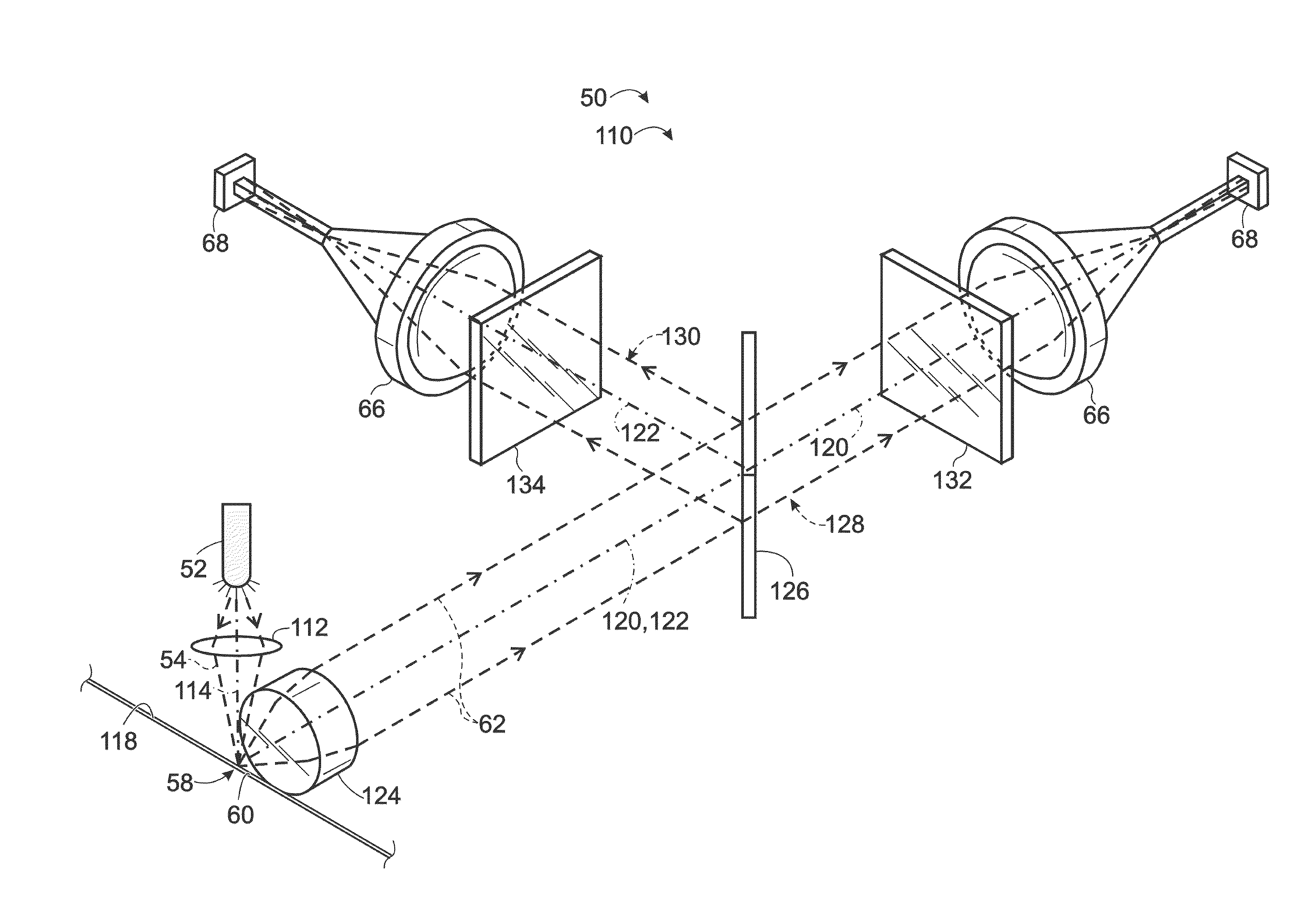
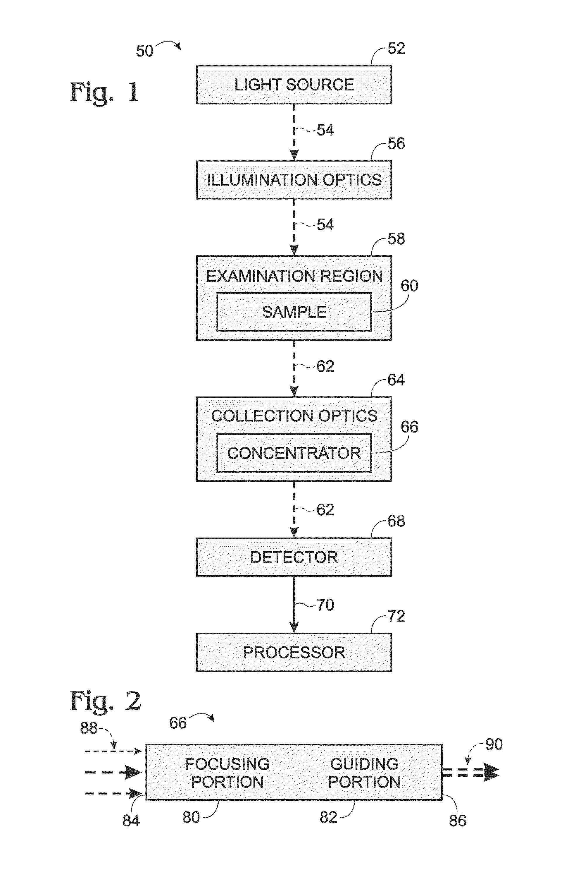
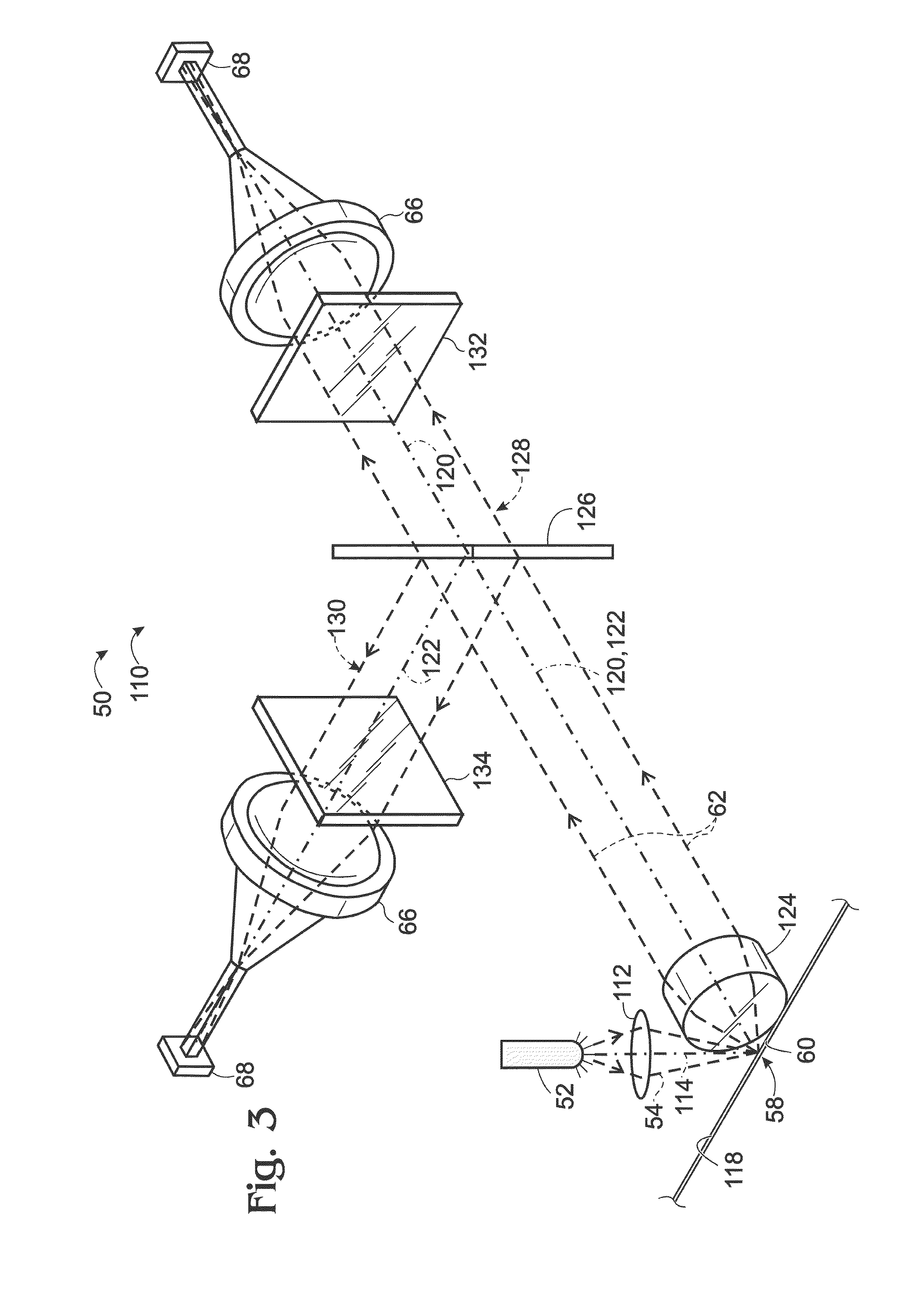
[0022]The present disclosure provides a detection system comprising an examination region, a one-piece optical element including a focusing portion to concentrate light received from the examination region and a guiding portion to homogenize light received from the focusing portion, and a detector configured to detect homogenized light received from the guiding portion.

[0023]The optical element, interchangeably termed a concentrator, may collect incident light from a relatively large area and direct it towards a light sensor with a comparatively small active area. The optical element may comprise a refractive focusing portion and a light guiding portion in one integral unit. The optical element may be a non-imaging optical device that delivers light from a relatively large input aperture (e.g., a round input aperture) to a relatively small output aperture (e.g., a rectangular output aperture), while homogenizing the intensity distribution of the light across the output aperture.

[002...


PUM

PropertyMeasurementUnit
sizeaaaaaaaaaa
sizeaaaaaaaaaa
sizeaaaaaaaaaa

Abstract

Detection system comprising an examination region, a one-piece optical element including a focusing portion to concentrate light received from the examination region and a guiding portion to homogenize light received from the focusing portion, and a detector configured to detect homogenized light received from the guiding portion.

Description

CROSS-REFERENCE TO PRIORITY APPLICATION[0001]This application is based upon and claims the benefit under 35 U.S.C. §119(e) of U.S. Provisional Patent Application Ser. No. 61 / 759,928, filed Feb. 1, 2013, which is incorporated herein by reference in its entirety for all purposes.[0002]CROSS-REFERENCES TO OTHER MATERIALS[0003]This application incorporates by reference in their entireties for all purposes the following patent documents: U.S. Pat. No. 7,041,481, issued May 9, 2006; U.S. Patent Application Publication No. 2010 / 0173394 A1, published Jul. 8, 2010; U.S. Patent Application Publication No. 2011 / 0217712 A1, published Sep. 8, 2011; U.S. Patent Application Publication No. 2012 / 0152369 A1, published Jun. 21, 2012; U.S. Patent Application Publication No. 2012 / 0190032 A1, published Jul. 26, 2012; and U.S. Patent Application Publication No. 2012 / 0194805 A1, published Aug. 2, 2012.INTRODUCTION[0004]Many biomedical applications rely on high-throughput assays of samples. For example, in...

Claims


Application Information

Patent Timeline
Patent Type & Authority Applications(United States)
IPC IPC(8): G01N21/01
CPCG01N21/01G01N15/1434G01N15/1459G01N21/645G01N35/08G01N2015/1006G01N2021/6478G01N2201/0806G02B6/0008G02B6/262G02B19/0028G02B19/0076
Inventor PRISTINSKI, DENISSTUMBO, DAVID P.
Owner BIO RAD LAB INC
Why Eureka
Try Eureka