
Clutch control apparatus

Active Publication Date: 2019-07-04
HONDA MOTOR CO LTD
View PDF0 Cites 2 Cited by
  • Summary
  • Abstract
  • Description
  • Claims
  • Application Information

AI Technical Summary

Benefits of technology

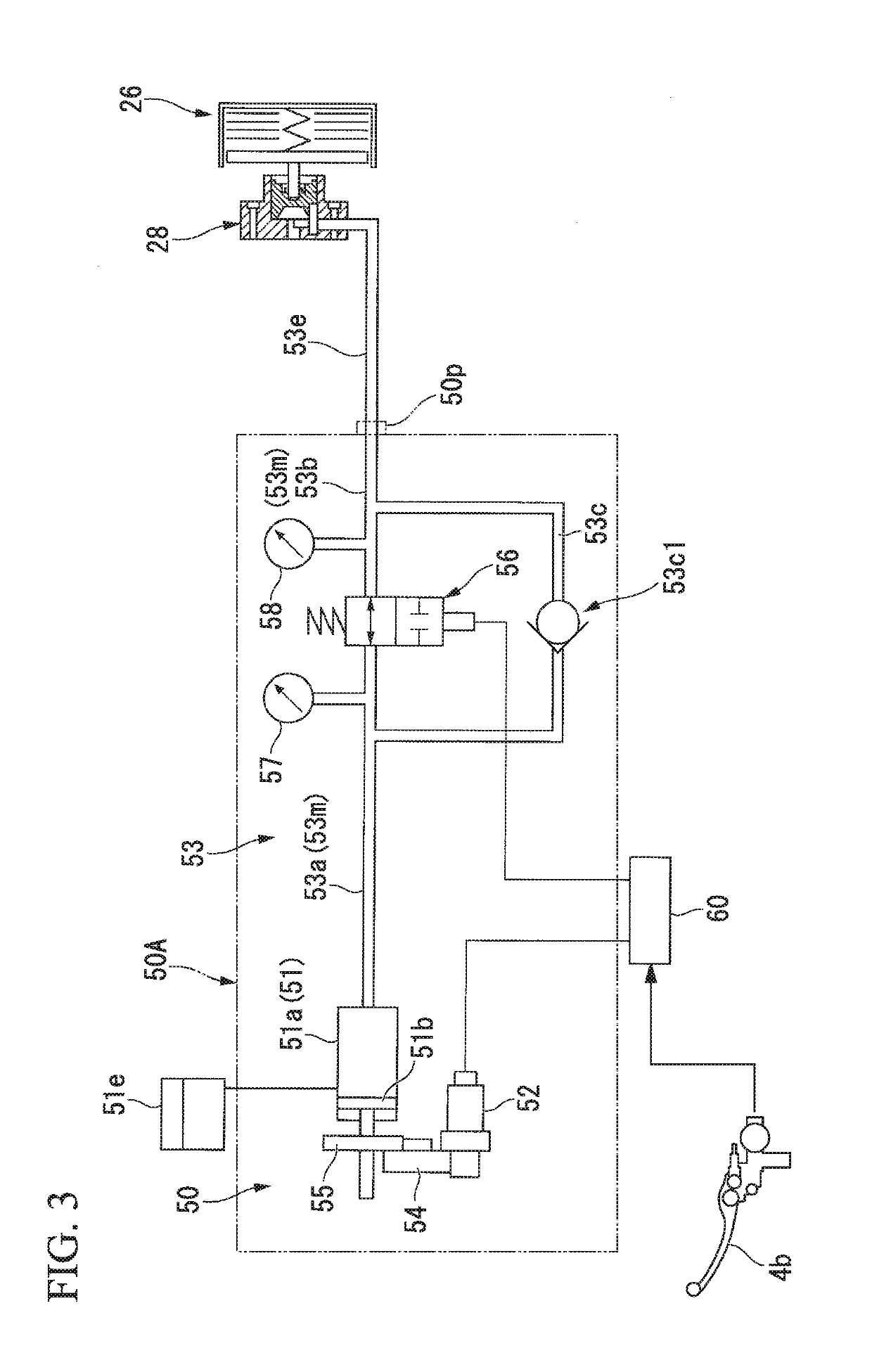
The patent text describes a method for controlling a vehicle's engine and transmission during downshifting. By decreasing the clutch capacity after downshifting, the engine rotational number can be suppressed to prevent over revolution after downshifting. The controller sets a clutch capacity that transmits a torque similar to the engine's friction torque, resulting in an appropriate traveling feeling without causing an idling running feeling for the driver. Additionally, the clutch capacity is controlled with hydraulic pressure to minimize the transmission delay of the driving force between the clutch actuator and the clutch device due to resistance to flow of hydraulic pressure. These technical effects improve the efficiency and driving experience of the vehicle during downshifting.

Problems solved by technology

However, in control of the related art, since performance of downshifting is not allowed when an engine rotational number is a predetermined high rotational number or more, it may be impossible for a driver to perform downshifting at a desired timing.

Method used


Image

  • Clutch control apparatus
  • Clutch control apparatus
  • Clutch control apparatus

Examples


Embodiment Construction

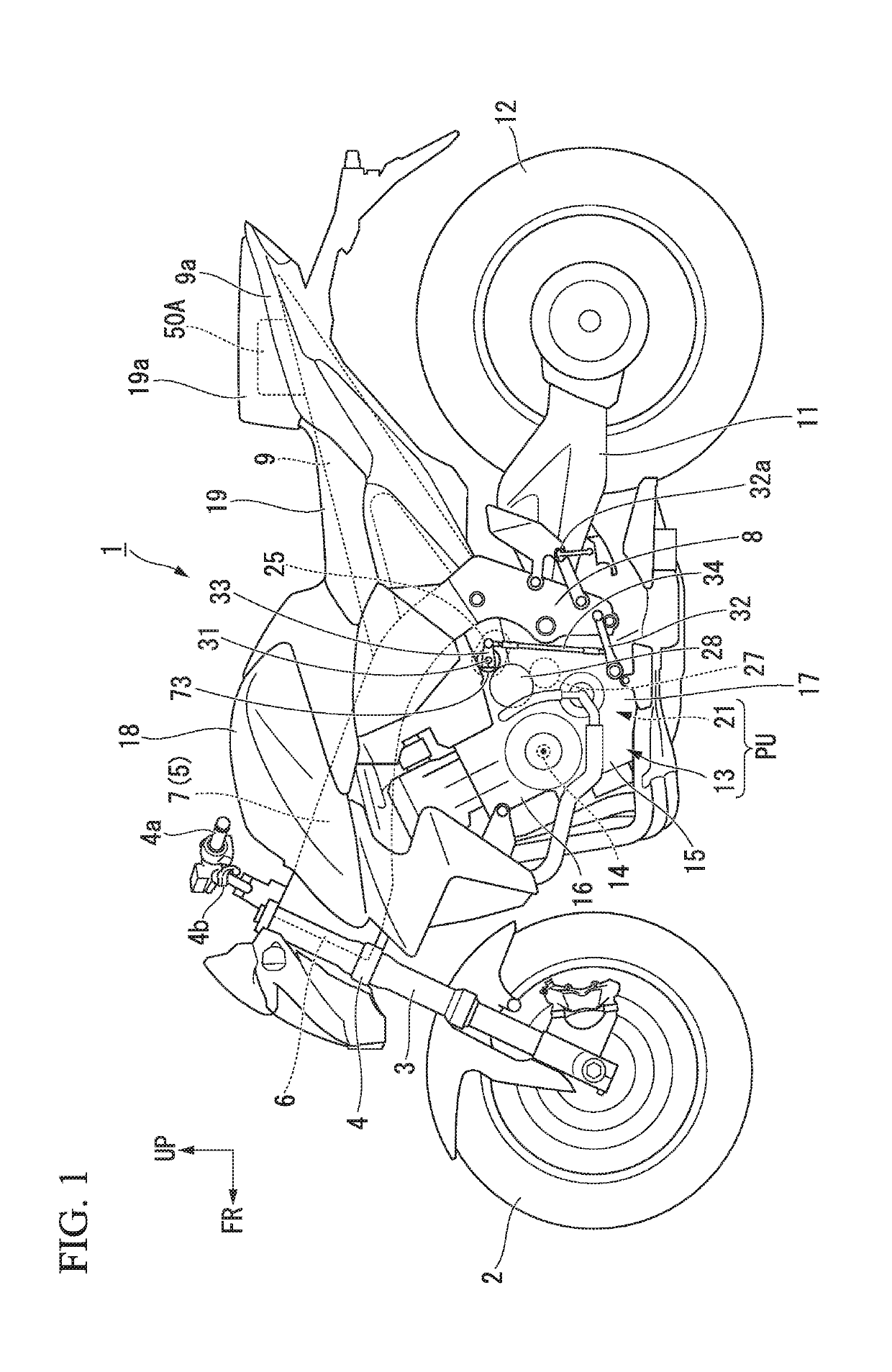
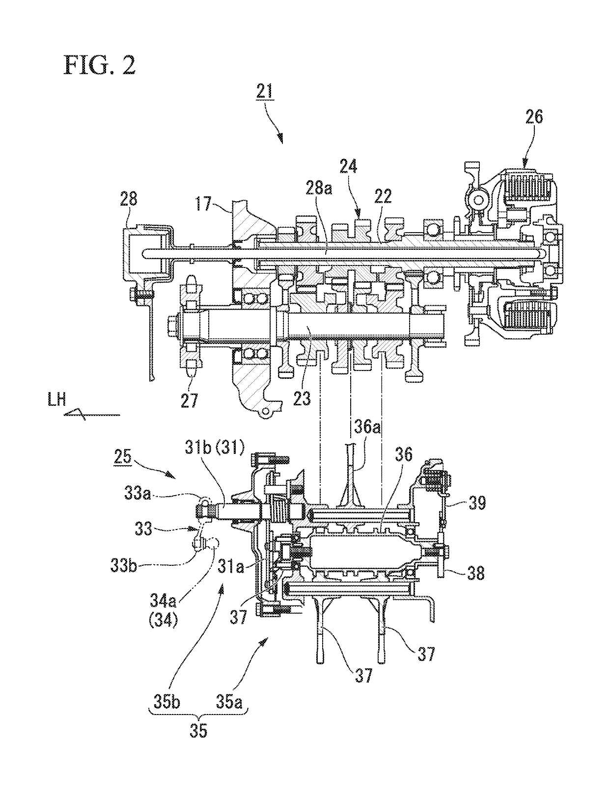
[0027]Hereinafter, an embodiment of the present invention will be described with reference to the accompanying drawings. Further, directions of forward, rearward, leftward, rightward, and so on, in the following description are the same as directions in a vehicle described below unless the context clearly indicates otherwise. In addition, in appropriate places in the drawings used in the following description, an arrow FR indicates a forward direction with respect to a vehicle, an arrow LH indicates a leftward direction with respect to the vehicle, and an arrow UP indicates an upward direction with respect to the vehicle.

[0028]As shown in FIG. 1, the embodiment is applied to a motorcycle 1 that is a saddle riding vehicle. A front wheel 2 of the motorcycle 1 is supported by lower end portions of a pair of left and right front forks 3.

[0029]Upper sections of the left and right front forks 3 are supported by a head pipe 6, which is a front end portion of a vehicle body frame 5, via a s...


PUM


Abstract

A clutch control device includes an engine, a gearbox, a clutch device configured to disconnect and connect power transmission between the engine and the gearbox, a clutch actuator configured to drive the clutch device and vary a clutch capacity, and an ECU configured to calculate a control target value of the clutch capacity, and the ECU determines whether an engine rotational number after downshifting by the gearbox enters a high rotation region and decreases the clutch capacity after downshifting when it is determined that the engine rotational number after downshifting enters the high rotation region.

Description

CROSS-REFERENCE TO RELATED APPLICATION[0001]Priority is claimed on Japanese Patent Application No. 2017-254248, filed Dec. 28, 2017, the content of which is incorporated herein by reference.BACKGROUND OF THE INVENTIONField of the Invention[0002]The present invention relates to a clutch control device.Description of Related Art[0003]In the related art, a configuration including a clutch device configured to disconnect and connect power transmission between an engine and a gearbox is known (for example, see Japanese Unexamined Patent Application, First Publication No. S60-139960).[0004]Japanese Unexamined Patent Application, First Publication No. S60-139960 discloses control of allowing downshifting to be performed when an engine rotational number is smaller than a predetermined high rotational number. Accordingly, over revolution (ultrahigh speed rotation) after downshifting is prevented.SUMMARY OF THE INVENTION[0005]However, in control of the related art, since performance of downsh...

Claims


Application Information

Patent Timeline
IPC IPC(8): F16D48/06F16H63/46
CPCF16D48/066F16H63/46F16D2500/1026F16D2500/10412F16D2500/1045F16D2500/1117F16D2500/3067F16D2500/30806F16D2500/50287F16D2500/7044F16D2500/70406F16H61/02F16H61/40F16H63/32F16D48/02F16D48/06F16D2500/31466F16D2500/5046
Inventor RYUZAKI, TATSUYAONO, JUNYAOZEKI, TAKASHI
Owner HONDA MOTOR CO LTD
Learn More