Time allocation method for synchronous Ethernet network

A time distribution, Ethernet technology, used in the field of synchronous Ethernet

Inactive Publication Date: 2006-04-19
SAMSUNG ELECTRONICS CO LTD
View PDF0 Cites 6 Cited by
  • Summary
  • Abstract
  • Description
  • Claims
  • Application Information

AI Technical Summary

Problems solved by technology

Therefore, during real-time data transfer, there is a delay of at least one transfer cycle

Method used


Image

  • Time allocation method for synchronous Ethernet network
  • Time allocation method for synchronous Ethernet network
  • Time allocation method for synchronous Ethernet network

Examples


Embodiment Construction

[0011] Hereinafter, embodiments of the present invention will be described in detail with reference to illustrations. It should be noted that, although shown in different drawings, the same or similar components in the drawings are denoted by the same reference numerals as far as possible. For brevity and clarity, detailed descriptions of known functions and structures incorporated herein will be omitted when it may obscure the subject matter of the present invention.

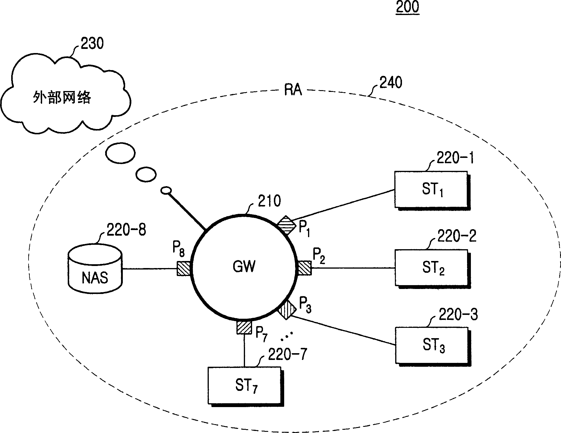
[0012] figure 2 is a view showing the structure of the synchronous Ethernet network 200 according to the embodiment of the present invention. The synchronous Ethernet network 200 is connected to an external network 230 such as the Internet, and includes a gateway 210, a first station (ST) to a seventh station (ST) 220-1-220-7, and a network attached storage 220-8. Here, the synchronous Ethernet network 200 covers a residential area (RA) such as an office or a home. Here, each site refers to a device (person...


PUM


Abstract

Disclosed is a time allocation method for a synchronous Ethernet network. The time allocation method for a synchronous Ethernet network including a gateway allocating time based on a cycle including an asynchronous part and a synchronous part and a plurality of network end points connected to the gateway, includes the steps of (a) preparing a plurality of time slots by multi-dividing the synchronous part in one cycle, and (b) allocating each time slot to a plurality of network end points participating in communication in a corresponding cycle in common.

Description

technical field [0001] The present invention relates to synchronous Ethernet, more specifically, to a synchronous Ethernet network and a time distribution method that can be used in the synchronous Ethernet network. Background technique [0002] Synchronous Ethernet is one of several technologies used to transmit real-time data such as voice / video data. Synchronous Ethernet is connected to an external network so as to cover a specific residential area, and contains gateways and stations (network terminal nodes connected to the gateway). Currently, synchronous Ethernet networks allocate transmission time based on a cycle that includes an asynchronous part and a synchronous part. The only standard for synchronous Ethernet networks stipulates that each cycle corresponds to 125 μs, and the synchronization between stations is realized according to the synchronization bits specified in the media access control (MAC) layer. [0003] figure 1 is a diagram showing a time allocatio...

Claims


Application Information

Patent Timeline
Patent Type & Authority Applications(China)
IPC IPC(8): H04L5/22
CPCH04L12/423H04L12/52
Inventor 权瑞远宋在涓林世伦
Owner SAMSUNG ELECTRONICS CO LTD
Why Eureka
Try Eureka