
Mobile communication system and mobile communication method

Inactive Publication Date: 2007-07-26
NEC CORP
View PDF4 Cites 36 Cited by
  • Summary
  • Abstract
  • Description
  • Claims
  • Application Information

AI Technical Summary

Benefits of technology

[0022] Also, the present invention has as another object to provide a technique for simplifying the control procedure when the terminal performs the three-party handover, to solve the above problems.
[0023] Further, the present invention has as further another object to provide a technique for minimizing the transmission delay in communication after handovers are successively performed, to solve the above problems.
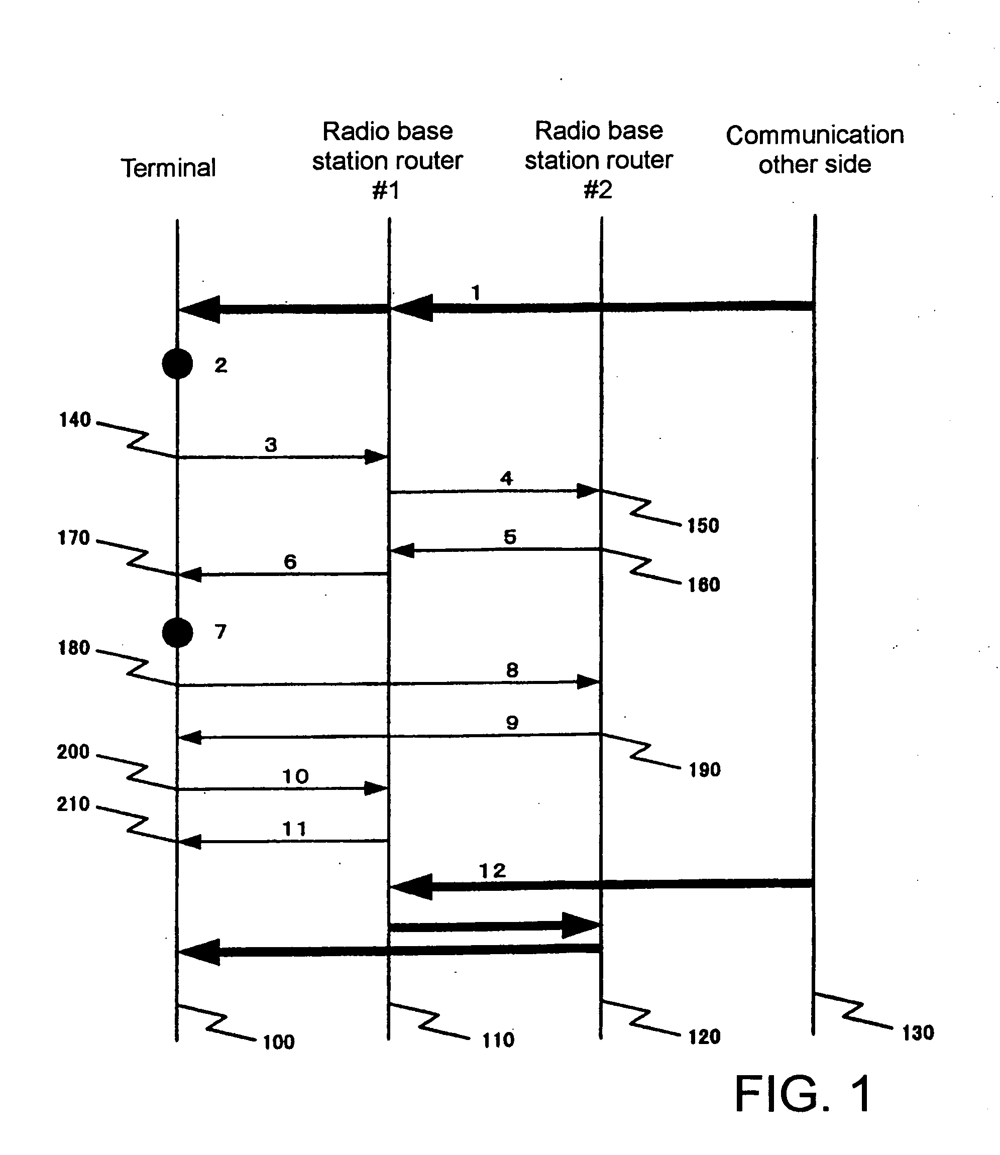
[0032] Further, according to the present invention, in a mobile communication system, tunnels managed by the radio base station router can be reduced, and the control of the radio base station routers can be simplified. As its reason, the packets addressed to the terminal are forwarded by using only two tunnels between the radio base station router serving as an anchor and a radio base station router from which a terminal moves out and between the anchor radio base station router and a radio base station router to which the terminal moves.
[0033] Also, according to the present invention, it is possible to minimize a transmission delay in communication after performing successively handovers. As its reason, the communication path after the terminal performs the three-party handover does not pass through the radio base station router from which the terminal moves out, but only through the anchor radio base station router and the radio base station router to which the terminal moves.

Problems solved by technology

There is a problem that a packet loss generates when the two-party handover is performed in FMIPv6.
However, in a case that the three-party handover is performed by using FMIPv6, when the radio base station router serving as an anchor switches a forwarding tunnel, there is a possibility that the order of the packets received by the terminal changes due to a difference in transmission path lengths.
Also, because, each of all radio base station routers has to control two forwarding tunnels, the control in the radio base station router is complicated.
Further, when the technique described in Document 1 is used, the order of the packets is not changed, however, it is necessary to control two forwarding tunnels between the radio base station router serving as an anchor and the radio base station router from which the terminal moves out and between the radio base station router from which the terminal moves out and the radio base station router to which the terminal moves, and therefore, the control in the radio base station router is complicated.
Also, since the forwarding path is a path through each radio base station router, the transmission delay becomes large.
Further, when handovers are continuously performed plural times, the complexity of management and the transmission delay are significantly increased.

Method used


Image

  • Mobile communication system and mobile communication method
  • Mobile communication system and mobile communication method
  • Mobile communication system and mobile communication method

Examples


first embodiment

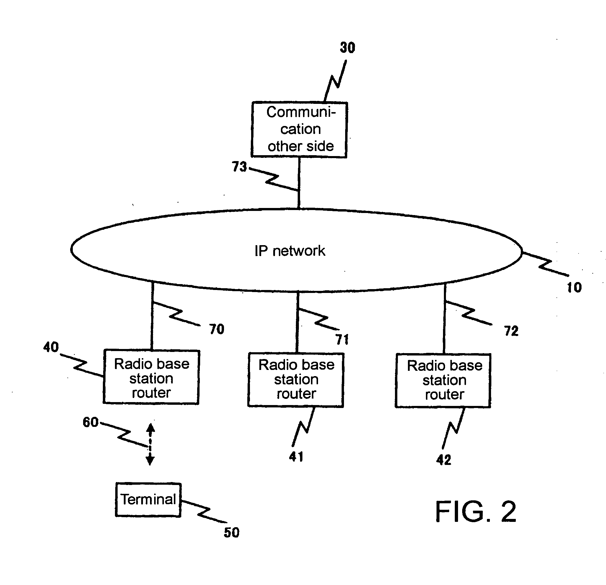
[0041] The mobile communication system according to the first embodiment of the present invention is explained with reference to the network configuration diagram shown in FIG. 2. As shown in FIG. 2, in the mobile communication system according the present embodiment, three radio base station routers 40, 41, 42 and communication other party 30 of a terminal are connected to Internet 10 through wired links 70 to 73, and terminal 50 communicates with communication other party 30 through wireless link 60.

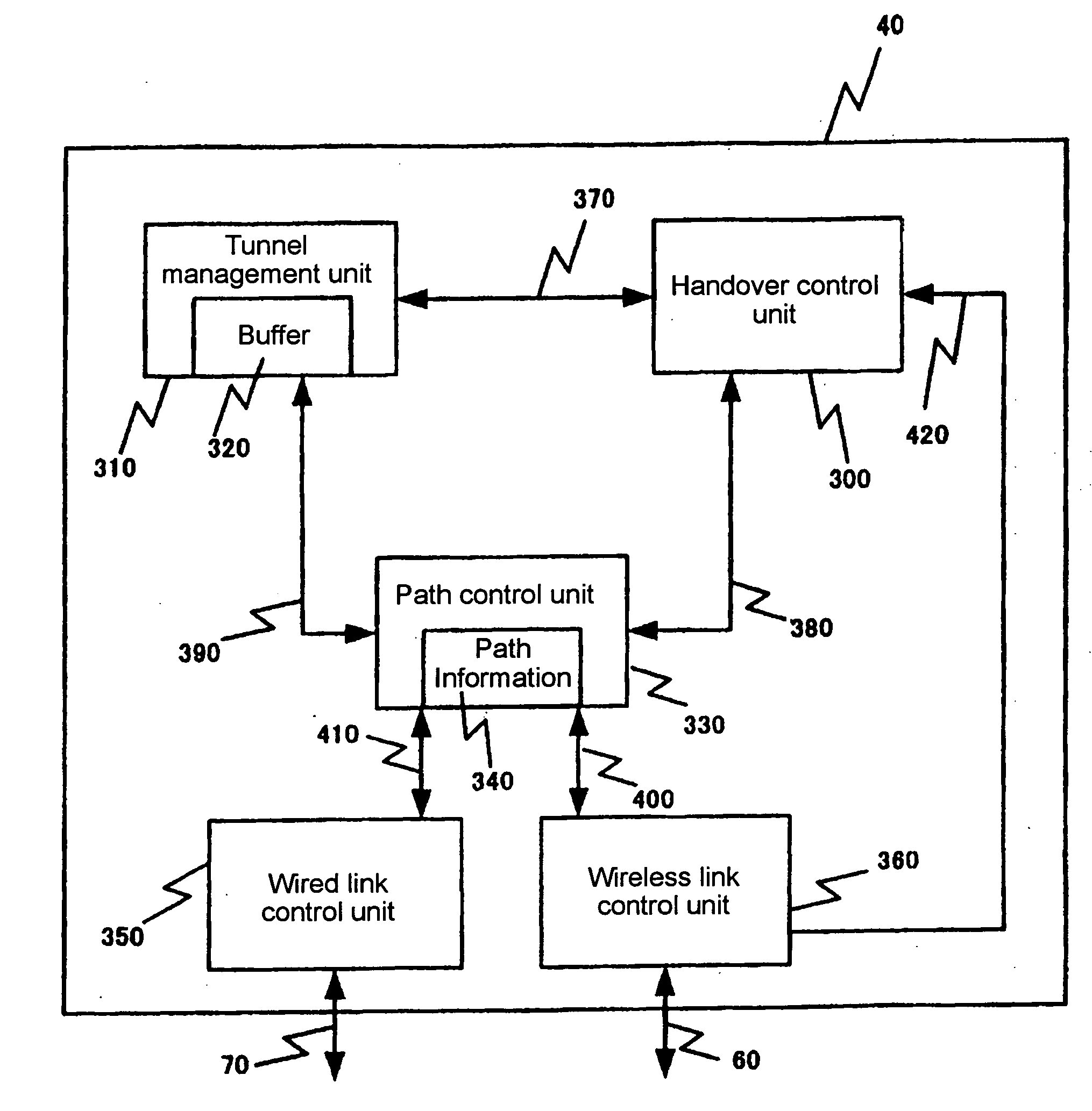
[0042] Successively, explanations are given of the configurations of terminal 50 and radio base station router 40 (or 41, 42) in the mobile communication system according to the present embodiment with reference to FIGS. 3 and 4. Incidentally, in FIG. 3, explanations are given while radio base station router 40 is taken as an example, and radio base station routers 41 and 42 are configured similarly.

[0043] As shown in FIG. 3, radio base station router 40 includes handover control uni...

second embodiment

[0067] Next, the second embodiment of the present invention is explained.

[0068] The radio base station and the terminal device according to the present invention may be configured by hardware, as is apparent from the explanations above, and also may be realized by a computer program.

[0069]FIG. 6 is a typical block diagram of an information processing unit implemented in the radio base station and the terminal device according to the present invention.

[0070] The information processing unit shown in FIG. 6 includes processor 601, program memory 602, and storage medium 603.

[0071] In the radio base station, processor 601 processes all or a part of functions of handover control unit 300, tunnel management unit 310, path control unit 330, wired link control unit 350, and wireless link control unit 360, which are described above, in accordance with the program stored in program memory 602. Also, all or a part of path information 340 is stored in storage medium 603.

[0072] Further, in t...


PUM


Abstract

There is provided a technique for ensuring that the order in which a terminal, when performing a three-party handover, receives packets is the same as the order in which a transmission terminal transmits those packets. When a terminal device successively handovers among a plurality of radio base station routers, a radio base station router serving as an anchor during the handovers buffers packets addressed to the terminal device, and forwards those packets by switching between a tunnel between a radio base station from which the terminal device moves out and the anchor radio base station and a tunnel between the anchor radio base station and a base station to which the terminal device moves.

Description

TECHNICAL FIELD [0001] The present invention relates to a handover technique in a mobile communication system using an IP network, and in particular, relates to a packet forwarding technique when a terminal in communication performs a handover. BACKGROUND ART [0002] In a mobile communication system using an IP network, when a terminal performs a handover to a different IP sub-network, the IP address of the terminal must be changed, and therefore IP level handover control is required. [0003] Currently, IETF (Internet Engineering Task Force) has studied Mobile Ipv6 and FMIPv6 (Fast Handovers for Mobile IPv6) for shortening the handover latency in Mobil Ipv6 as IP level handover techniques. [0004] Since, FMIPv6 is provided with simple routers except edges in the IP mobile communication network, only an access router at the edge is provided with a handover control function and supports the handover for the terminal. Details of Mobile IPv6 and FMIPv6 are described in draft-ietf-mobileip-...

Claims


Application Information

Patent Timeline
IPC IPC(8): H04B1/26H04B7/26H04W36/02H04W36/08H04W36/30H04W92/20
CPCH04W36/02H04W92/20H04W36/30H04W36/08
Inventor SUDA, YUKINORI
Owner NEC CORP
Learn More