Arrangement for a Screw Compressor of a Utility Vehicle

Inactive Publication Date: 2019-07-11
KNORR-BREMSE SYST FUER NUTZFAHRZEUGE GMBH
View PDF0 Cites 0 Cited by
  • Summary
  • Abstract
  • Description
  • Claims
  • Application Information

AI Technical Summary

Benefits of technology

[0017]Provision may furthermore be made whereby the middle of the three baffle plate receiving apertures is arranged outside the imaginary line that connects the two other baffle plate receiving apertures. In this way, it is made possible to realize relatively simple clamping because, in the middle region, the bending force is formed which then serves for clamping of the baffle plate in the baffle plate receiving apertures or in the housing component of the screw compressor. The bending forces required for the assembly process, which can be imparted for this purpose, are furthermore relatively easy to apply because the baffle plate has to be bent in the middle, and then an insertion can be performed relatively easily.
[0018]The fingers of the baffle plate may be substantially in alignment in the non-inserted and non-assembled state. It is contemplated in particular for the baffle plate, in the non-bent state, to be a relativel

Problems solved by technology

Furthermore, the oil cooler must be mechanically accommodated and fastened, either by way of brackets situated in the

Method used


Image

  • Arrangement for a Screw Compressor of a Utility Vehicle
  • Arrangement for a Screw Compressor of a Utility Vehicle
  • Arrangement for a Screw Compressor of a Utility Vehicle

Examples


Example

DETAILED DESCRIPTION OF THE DRAWINGS

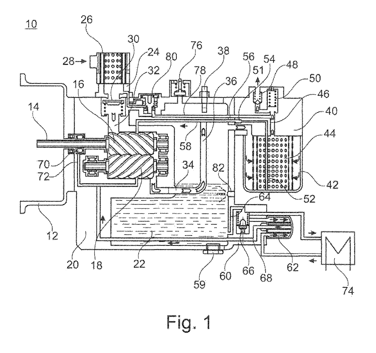
[0025]FIG. 1 shows, in a schematic sectional illustration, a screw compressor 10 in the context of an exemplary embodiment of the present invention.

[0026]The screw compressor 10 has a fastening flange 12 for the mechanical fastening of the screw compressor 10 to an electric motor (not shown in any more detail here).

[0027]What is shown, however, is the input shaft 14, by which the torque from the electric motor is transmitted to one of the two screws 16 and 18, specifically the screw 16.

[0028]The screw 18 meshes with the screw 16 and is driven by means of the latter.

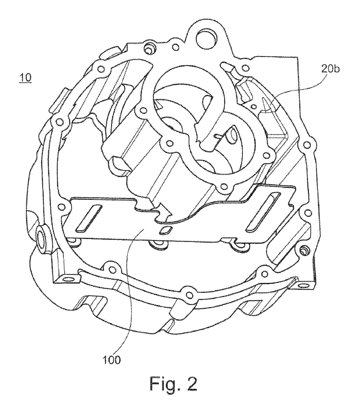
[0029]The screw compressor 10 has a housing 20 in which the main components of the screw compressor 10 are accommodated.

[0030]The housing 20 is filled with oil 22.

[0031]At the air inlet side, an inlet connector 24 is provided on the housing 20 of the screw compressor 10. The inlet connector 24 is in this case designed such that an air filter 26 is arranged at said inlet connector. Furth...


PUM


Abstract

An arrangement for a screw compressor of a utility vehicle has at least one housing part of the screw compressor and a baffle. The housing component has at least three baffle receptacle recesses, wherein at least one baffle receptacle recess is arranged outside an imaginary line connecting the two other baffle receptacle recesses. The baffle has at least three fingers which, in the assembled state of the arrangement, are each inserted in a baffle receptacle recess associated with the respective finger.

Description

CROSS REFERENCE TO RELATED APPLICATIONS[0001]This application is a continuation of PCT International Application No. PCT / EP2017 / 073576, filed Sep. 19, 2017, which claims priority under 35 U.S.C. § 119 from German Patent Application No. 10 2016 011 444.4, filed Sep. 21, 2016, the entire disclosures of which are herein expressly incorporated by reference.BACKGROUND AND SUMMARY OF THE INVENTION[0002]The present invention relates to an arrangement for a screw compressor of a utility vehicle, comprising at least one housing component of the screw compressor and a baffle plate.[0003]Screw compressors for utility vehicles are already known from the prior art. Such screw compressors are used, for example, to provide the compressed air required for the brake system of the utility vehicle.[0004]In this context, in particular oil-filled compressors, in particular also screw compressors, are known, in the case of which it is necessary to regulate the oil temperature. This is generally realized ...

Claims


Application Information

Patent Timeline
IPC IPC(8): F04C18/16F04C29/04
CPCF04C18/16F04C29/04F04C2240/80F04C2210/14F04C29/026F04C2240/809F04C29/02F04C2210/1005F04C2210/221F05B2210/12F05B2210/16F05B2260/98
Inventor HEBRARD, GILLESMARESCOT, JEAN-BAPTISTEMELLAR, JOERGWEINHOLD, THOMAS
Owner KNORR-BREMSE SYST FUER NUTZFAHRZEUGE GMBH
Why Eureka
Try Eureka