

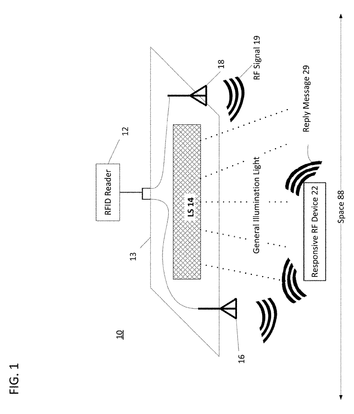
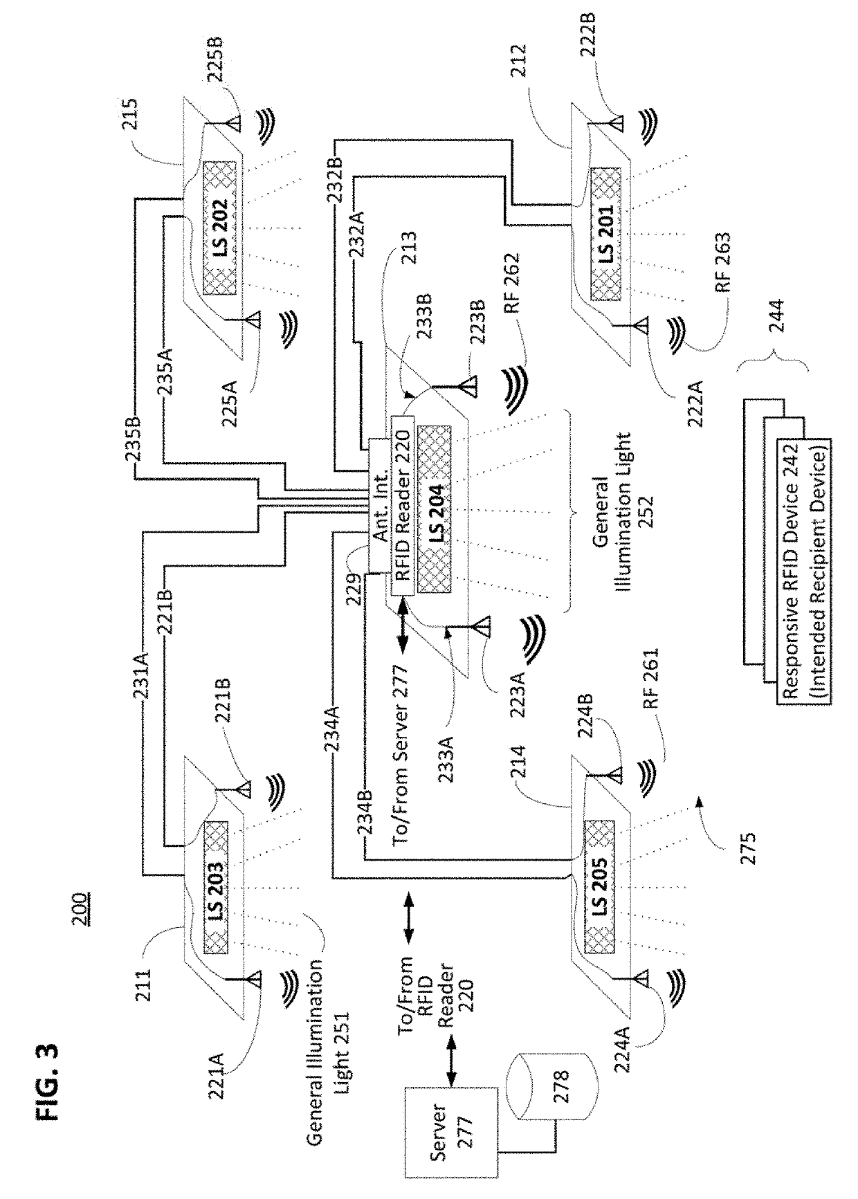
RFID system with antenna integrated in a luminaire
a technology of radio frequency identification and luminaire, which is applied in the direction of individual entry/exit registers, instruments, electromagnetic radiation sensing, etc., can solve the problems of high implementation cost and redundant devices, and achieve the effect of improving the utilization rate and accuracy and efficiency of rfid systems
- Summary
- Abstract
- Description
- Claims
- Application Information
AI Technical Summary
Benefits of technology
Problems solved by technology
Method used
Image


Examples
Embodiment Construction
[0030]In the following detailed description, numerous specific details are set forth by way of examples in order to provide a thorough understanding of the relevant teachings. However, it should be apparent that the present teachings may be practiced without such details. In other instances, well known methods, procedures, components, and / or circuitry have been described at a relatively high-level, without detail, in order to avoid unnecessarily obscuring aspects of the present teachings.
[0031]A need exists for improvement in enabling cost effective and accurate asset tag tracking utilizing a regionalized RFID reader configuration utilizing a distributed set of antennas. Such a regionalized RFID reader covers a larger region in comparison to an ordinary RFID reader and antenna combination. The following discussion explains the structure and function of a regionalized RFID reader configuration that utilizes a central RFID reader coupled to a number of antennas dispersed around the RF...
PUM
 Abstract
Description
Claims
Application Information