
Fastening Device

a technology of fastening device and zipper, which is applied in the field of fasteners, can solve the problems of zipper, button and velcro technology that suffer from several drawbacks, can not be easily retracted, and can be loud when, so as to prevent any relative rotational movement and facilitate a smooth engagement of the tooth

Active Publication Date: 2019-07-18
MORAR FLORIN
View PDF8 Cites 1 Cited by
  • Summary
  • Abstract
  • Description
  • Claims
  • Application Information

AI Technical Summary

Benefits of technology

The technology described in this patent allows for the secure and stable engagement of tooth and socket pairs through rotational movement. The tooth is fully received within the socket, with the first and second surfaces of the tooth in close contact with the inner walls of the socket to prevent movement parallel to the first axis. Additionally, the tooth and socket are prevented from separating along the second axis by a portion of the socket, ensuring locking of the tooth and socket in place. The design also takes into account the natural curved shape of the tooth and socket, making the engagement process smoother and more comfortable for the patient.

Problems solved by technology

However, zipper, button, and Velcro technologies suffer from several drawbacks.
Zippers can fail under substantial load and frequently get stuck when material gets caught between the teeth.
Also zippers can be loud when fastening or unfastening.
Similarly, snaps / buttons can break or become inoperable when dirt or debris get caught within, making them far less effective.
Velcro applications also have similar drawbacks, create noise when engaging and disengaging and becoming less effective over time after catching dirt and debris.
Further, the clothing or other item's material often gets caught in the Velcro, sometimes causing damage.

Method used


Image

  • Fastening Device
  • Fastening Device
  • Fastening Device

Examples


Embodiment Construction

[0057]The following detailed description illustrates the technology by way of example, not by way of limitation of the principles of the invention. This description will enable one skilled in the art to make and use the technology, and describes several embodiments, adaptations, variations, alternatives and uses of the invention, including what is presently believed to be the best mode of carrying out the invention. One skilled in the art will recognize alternative variations and arrangements, and the present technology is not limited to those embodiments described hereinafter.

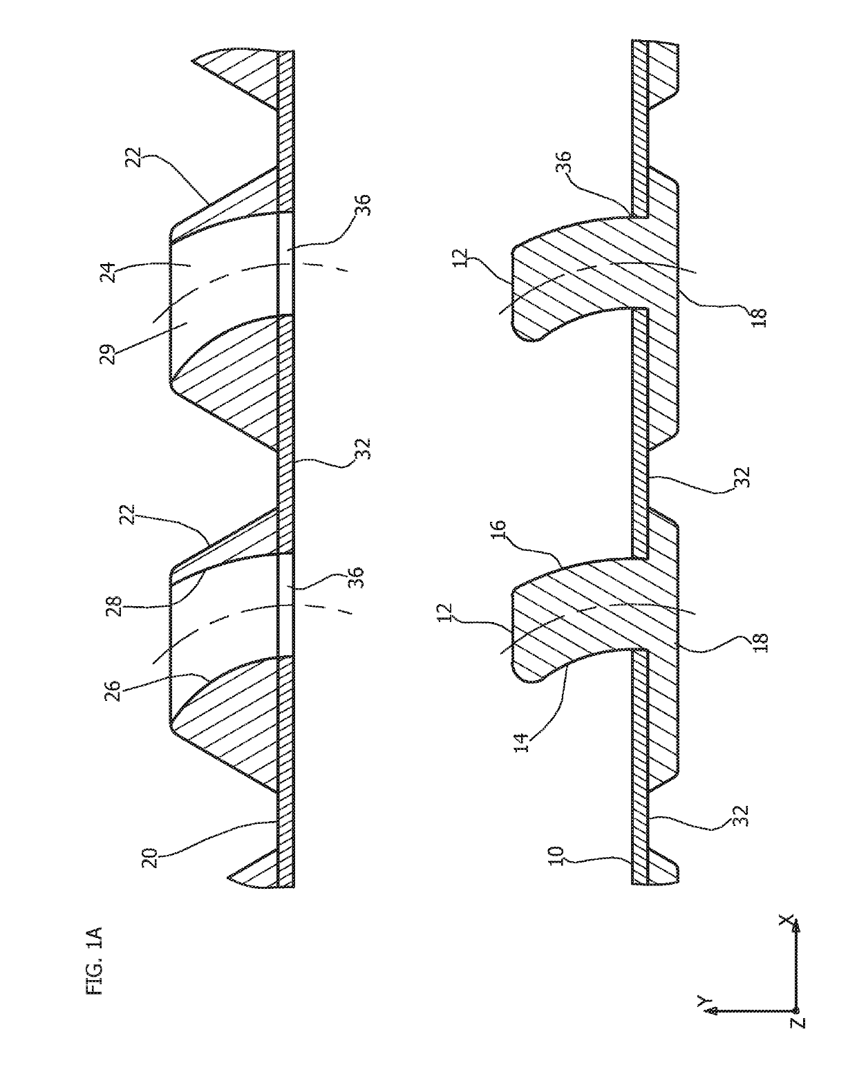
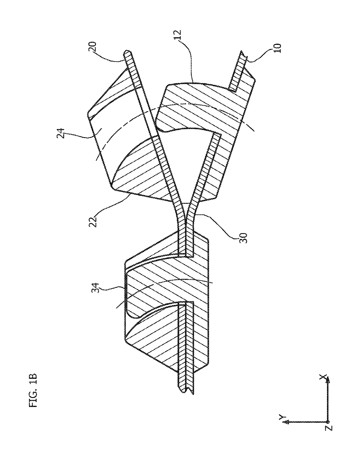
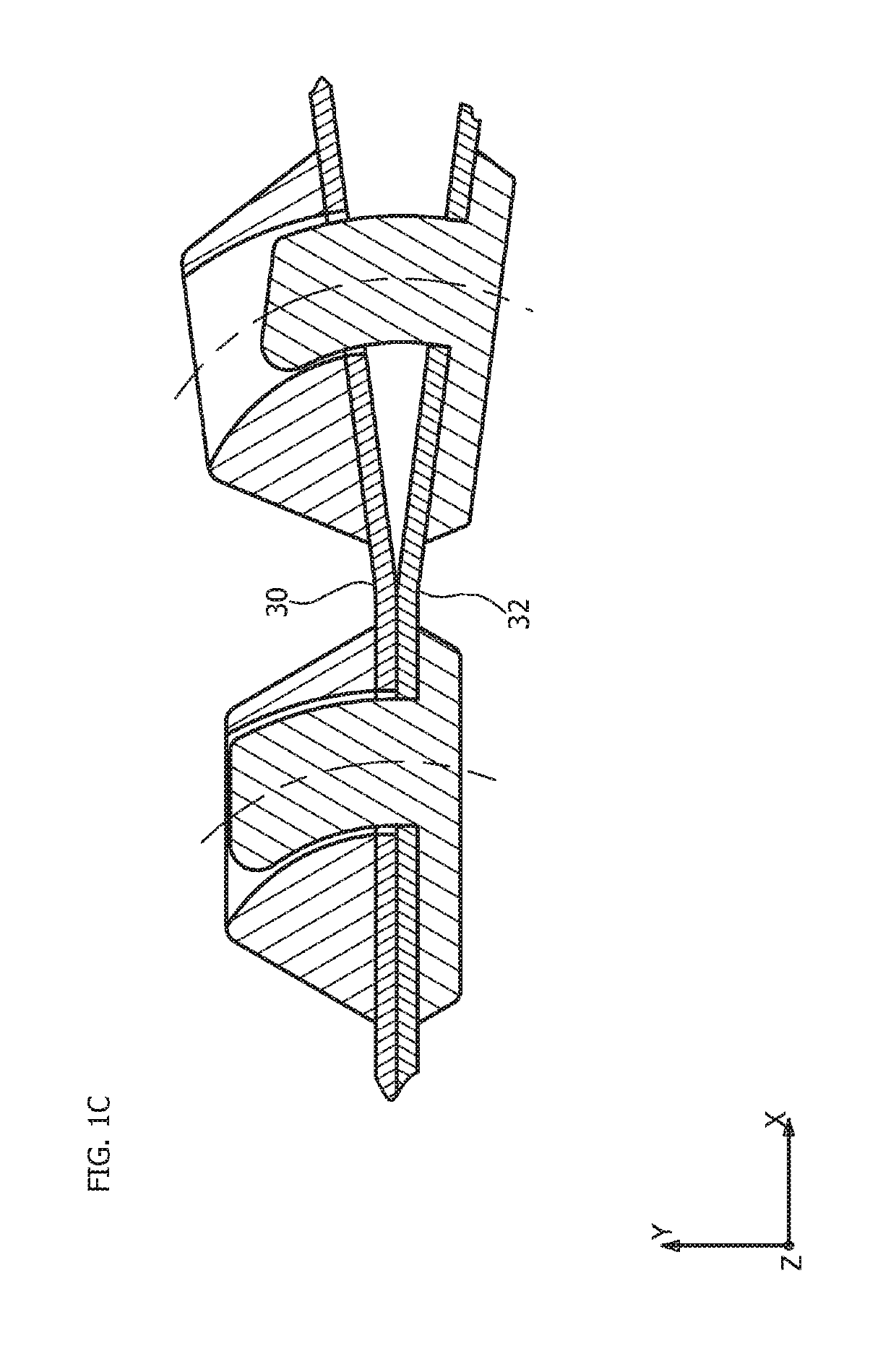
[0058]The fastening device described herein is intended as an alternative to the traditional fastening devices used on clothing and the like, including zippers, buttons, Velcro (hook and loop), etc. The technology employs first and second fastening members, which may be attached to, or incorporated into, parts of an article to be joined such as, for example, wearable articles or other articles. Like a zipper, ...


PUM

PropertyMeasurementUnit
center of curvatureaaaaaaaaaa
curvatureaaaaaaaaaa
flexibleaaaaaaaaaa

Abstract

A fastening device has a first fastening member with a plurality of teeth and a second fastening member with a plurality of sockets which are sequentially engagable in tooth and socket pairs in an engagement direction by relative rotation of the tooth and socket. Each tooth has a first surface and a second surface fixed relative to the first surface. Each socket has a recess defined by a first wall and second wall fixed relative to the first wall. Upon engagement, the first and second surfaces of the tooth abut the respective first and second walls of the recess and prevent relative movement of the tooth in the engagement direction and a portion of the first wall of the socket closely abutting the first surface of the tooth is disposed between the tooth and a portion of the first fastening member and prevents relative separation of the tooth and socket.

Description

FIELD OF THE INVENTION[0001]The technology relates to the field of fasteners for use, for example, on clothing, luggage, outdoor gear, etc. More specifically, the technology discloses a fastener for such uses as an alternative to zippers, snaps or buttons, and hook and loop (Velcro) applications commonly used.BACKGROUND OF THE INVENTION[0002]Many applications require the ability to easily fasten and unfasten two separate pieces of an article. Typical examples include clothing and jackets as well as luggage, purses, and other transportation receptacles, sporting goods, camping gear such as tents and sleeping bags, belts and straps, and other applications. Commonly, such items employ zippers, snaps or buttons, or Velcro fasteners to facilitate this need. Examples of such technology are depicted in U.S. Pat. Nos. 3,941,383, 3,969,794, 4,546,026, 4,677,011, 5,640,744, 6,243,927, 6,393,678, and 6,481,064. The teachings of these documents are hereby incorporated in their entireties.[0003]...

Claims


Application Information

Patent Timeline
Patent Type & Authority Applications(United States)
IPC IPC(8): A44B18/00
CPCA44B18/0015A44B17/0058A44B18/0049A44B19/08B23B3/06
Inventor MORAR, FLORIN
Owner MORAR FLORIN
Learn More