
Docking Device for Aortic Valve Replacement

a technology for aortic valves and aortic valves, which is applied in the field of aortic valve replacement docking devices, can solve the problems of valve embolism being usually catastrophic and difficult to properly trea

Inactive Publication Date: 2019-07-25
MCDONALD MICHAEL B
View PDF0 Cites 2 Cited by
  • Summary
  • Abstract
  • Description
  • Claims
  • Application Information

AI Technical Summary

Benefits of technology

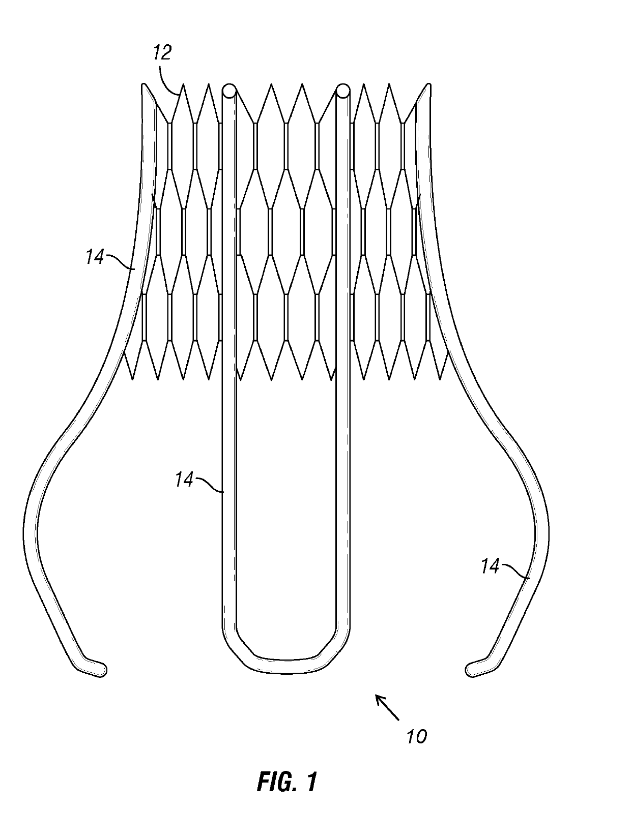
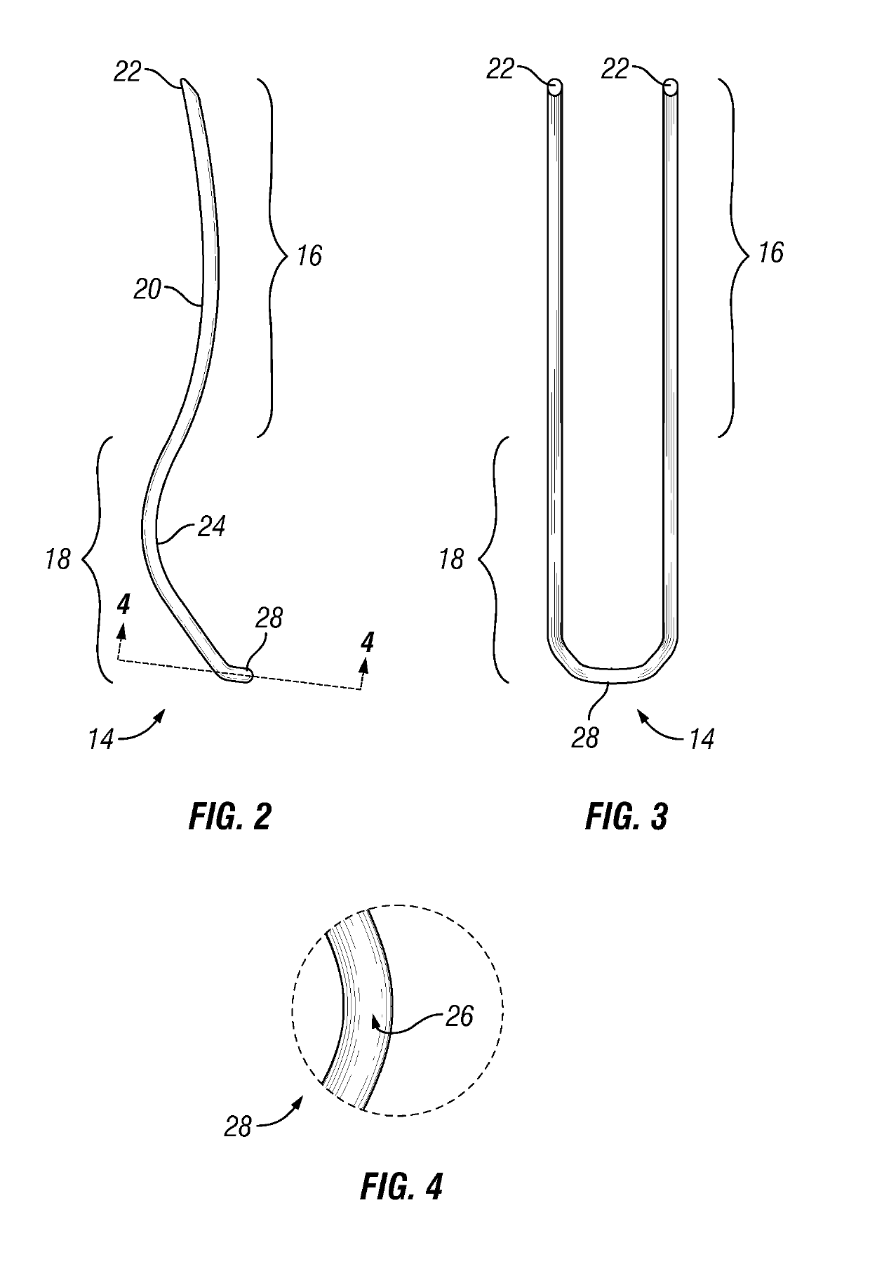
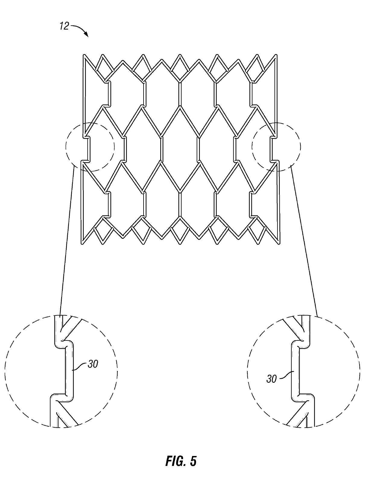
The patent describes a docking device that can be used to secure an aortic valve replacement in a patient. The docking device includes a lattice that forms a tubular framework and is expandable. The lattice has struts attached around it, which can be positioned in the ascending aorta and the Sinus of Valsalva of the patient. The struts have upper and lower parts, with the lower part having an elongated loop formed by a doubling of a wire. The lower part can be shaped longitudinally as a curve protruding outward and inward relative to the tubular framework. The docking device can be expanded and locked onto the aortic valve replacement using inner protrusions on the lattice that pinch the aortic valve leaflets between the docking device and the replacement. The technical effect of the docking device is to provide a secure and reliable platform for aortic valve replacement surgery.

Problems solved by technology

This lack of calcium to grab the valve can result in difficulty properly positioning the transcatheter aortic valve replacement and holding it in place.
Valve embolization is usually catastrophic.

Method used


Image

  • Docking Device for Aortic Valve Replacement
  • Docking Device for Aortic Valve Replacement
  • Docking Device for Aortic Valve Replacement

Examples


Embodiment Construction

[0024]It is to be understood that the following disclosure describes several exemplary embodiments for implementing different features, structures, or functions of the invention. Exemplary embodiments of components, arrangements, and configurations are described below to simplify the disclosure; however, these exemplary embodiments are provided merely as examples and are not intended to limit the scope of the invention. Additionally, the disclosure may repeat reference numerals and / or letters in the various exemplary embodiments and across the Figures provided herein. This repetition is for the purpose of simplicity and clarity and does not in itself dictate a relationship between the various exemplary embodiments and / or configurations discussed in the various Figures. Finally, the exemplary embodiments presented below may be combined in any combination of ways, i.e., any element from one exemplary embodiment may be used in any other exemplary embodiment, without departing from the ...


PUM


Abstract

A docking device for aortic valve replacements is a self-expanding nitinol structure including a lattice forming a tubular (e.g., cylindrical) upper framework or cage, and three struts forming a lower structure. The struts are formed by elongated loops that are attached to the lattice or that are an integral part of the upper framework. The struts extend down beneath the lattice, eventually forming “feet” to anchor at the base of the aortic cusps. The docking device can be positioned near a sinotubular junction of a patient. An aortic valve replacement is locked inside the docking device.

Description

CROSS-REFERENCE TO RELATED APPLICATIONS[0001]This application claims the benefit of priority to U.S. provisional application Ser. No. 62 / 619,448 filed on Jan. 19, 2018, which is incorporated herein by reference.[0002]This application also claims the of priority to U.S. provisional application Ser. No. 62 / 627,910 filed on Feb. 8, 2018, which is incorporated herein by reference.BACKGROUND[0003]This disclosure relates generally to methods and apparatus for locking an aortic valve replacement near a sinotubular junction of a patient.[0004]Most of the present percutaneous aortic valve replacements (also referred to as transcatheter aortic valves) are designed to be used in patients suffering from aortic stenosis. In almost all cases of aortic stenosis, there is a significant amount of calcium in the aortic valve. This deposition of calcium is the main feature that holds these aortic valve replacements in place in the aortic annulus.[0005]Patients with aortic insufficiency usually do not ...

Claims


Application Information

Patent Timeline
IPC IPC(8): A61F2/24
CPCA61F2/2409A61F2210/0014A61F2/2418
Inventor MCDONALD, MICHAEL B.
Owner MCDONALD MICHAEL B
Learn More