
Transcatheter valve stent anchors

a technology of transcatheter valve and stent body, which is applied in the field of prosthetic heart valves, can solve the problems of affecting the function of the mitral valve, affecting the design of the expandable stent body and valve, and disrupting the electrical conduction system

Active Publication Date: 2017-03-21
ST JUDE MEDICAL LLC
View PDF6 Cites 0 Cited by
  • Summary
  • Abstract
  • Description
  • Claims
  • Application Information

AI Technical Summary

Benefits of technology

The patent describes a stent for replacement of a damaged heart valve. The stent has a collapsed configuration for easy placement and an expanded configuration to hold its position. It includes a plurality of closed cells and an anchor feature that engages with the heart to secure the stent. The anchor feature can be connected to the stent at different locations and can have a flaring engagement portion to securely hold the stent in place. The stent can be made from a variety of materials and can be coated with biocompatible substances. The technical effect of this invention is improved stability and engagement with the heart tissue to ensure the stent stays in place and performs its function correctly.

Problems solved by technology

There are significant challenges in the design of an expandable stent body and valve.
Excessive forces on the annulus of the native aortic valve can disrupt the electrical conduction system of the heart and also can impair the functioning of the mitral valve.
These issues are complicated by the fact that the native valve leaflets ordinarily are left in place when an expandable prosthetic valve is implanted.
For example, patients with calcified or stenotic aortic valves may not be treated well with the current collapsible valve designs, and may encounter problems such as (1) perivalvular leakage (PV leak), (2) valve migration, (3) mitral valve impingement, (4) conduction system disruption, etc., all of which can lead to adverse clinical outcomes.
If a valve is not designed to function in these environments, it may result in several types of adverse events described above since distortion of the valve can result in the loss of valve coaptation, loss of valve apposition, and overall higher stresses.

Method used


Image

  • Transcatheter valve stent anchors
  • Transcatheter valve stent anchors
  • Transcatheter valve stent anchors

Examples


Embodiment Construction

[0022]While the present invention will be described more fully hereinafter with reference to the accompanying drawings, in which particular embodiments of stents and methods of delivery are shown, it is to be understood at the outset that persons skilled in the art may modify the invention herein described while achieving the functions and results of this invention. Accordingly, the descriptions that follow are to be understood as illustrative and exemplary of specific structures, aspects and features within the broad scope of the present invention and not as limiting of such broad scope. Like numbers refer to similar features of like elements throughout.

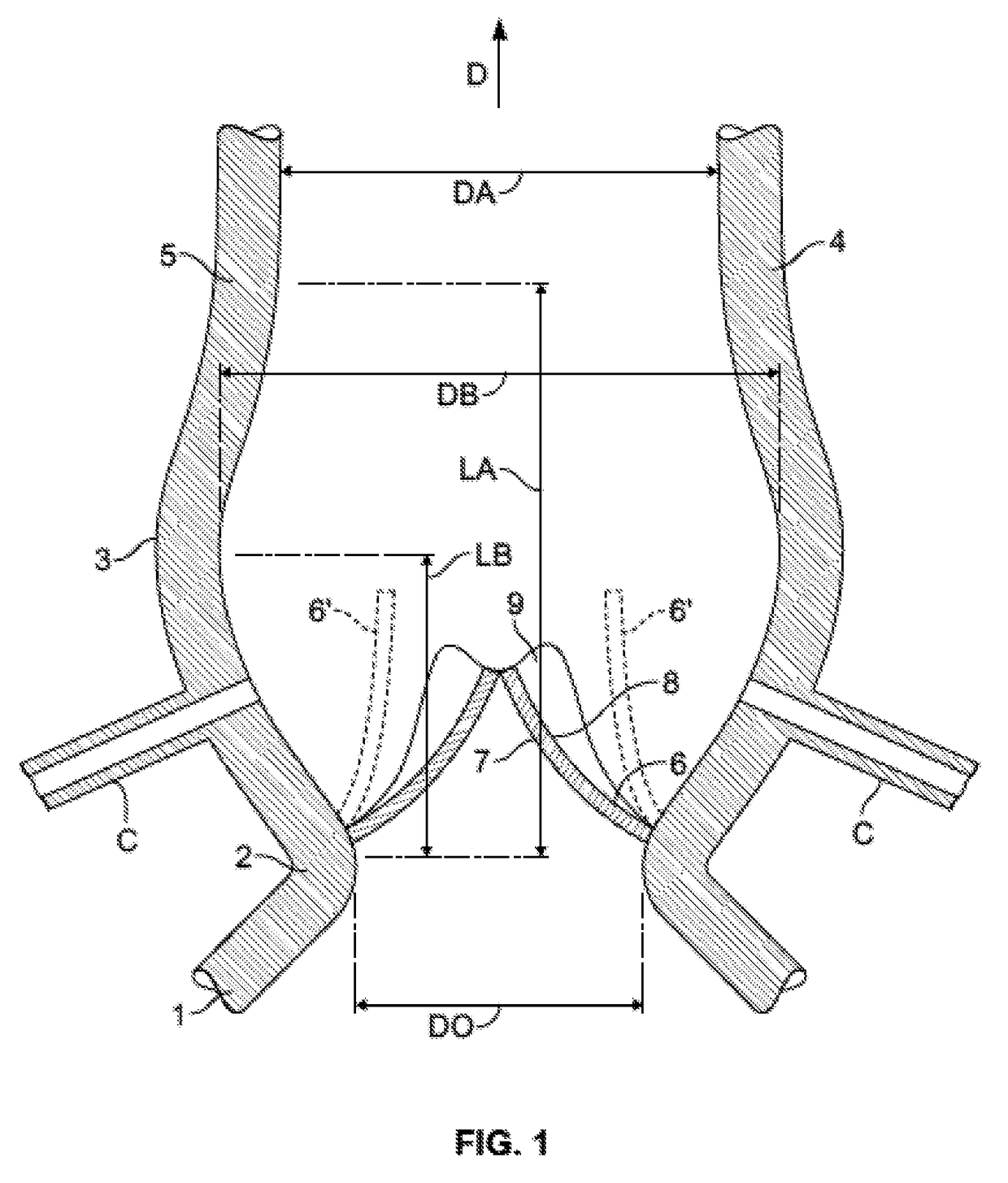
[0023]FIG. 1 is a simplified view of the geometry or anatomy of the aortic root tissue in a typical human heart. The left ventricular outflow tract (LVOT) 1 communicates with the ascending aorta 5 through the annulus 2 of the native aortic valve and the Valsalva sinus 3. The sinus joins the aorta at the sinotubular junction (STJ) 4....


PUM


Abstract

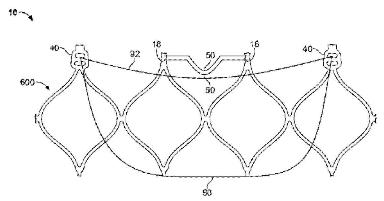
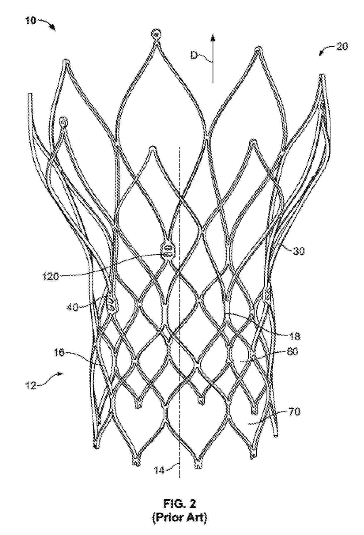
A stent for use in a prosthetic heart valve has a plurality of expandable and collapsible closed cells, a portion of which form an annulus section adapted for placement within the annulus of the native heart valve. Anchor features of the stent residing within at least some closed cells are adapted to engage tissue of the heart, including native valve leaflets, the sinotubular junction, or another implanted device when the prosthetic valve is implanted in the heart. The anchor features may help to retain the prosthetic valve in position, without interfering with the opening and closing of the valve leaflets. Furthermore, the anchor features may be configured to allow the stent to be resheathed into a delivery device after the portion of the stent with the anchor feature has expanded out of the delivery device.

Description

CROSS-REFERENCE TO RELATED APPLICATIONS[0001]The present application claims the benefit of the filing date of U.S. Provisional Patent Application No. 61 / 766,783 filed Feb. 20, 2013, the disclosure of which is hereby incorporated by reference herein.FIELD OF THE INVENTION[0002]The present invention is directed to prosthetic heart valves for replacement of native heart valves, to stents for use in such prosthetic heart valves, and to methods of treating patients with such prosthetic heart valves.BACKGROUND OF THE INVENTION[0003]Certain prosthetic heart valves incorporate an expandable stent body and valve elements such as prosthetic valve leaflets mounted to the stent body. Valves of this type may be implanted in the heart by advancing the valve into the body of the patient with the stent body in a collapsed condition in which the stent body has a relatively small diameter. Once the valve is positioned at the desired implantation site, the stent body is brought to an expanded conditio...

Claims


Application Information

Patent Timeline
Patent Type & Authority Patents(United States)
IPC IPC(8): A61F2/06A61F2/24
CPCA61F2/2418A61F2/2436A61F2220/0008A61F2230/005A61F2230/0054A61F2250/006A61F2250/0039A61F2230/0013
Inventor BRAIDO, PETER N.
Owner ST JUDE MEDICAL LLC
Learn More