Pump diaphragm

a diaphragm and pump technology, applied in the field of pump diaphragms, can solve the problems of weakening the bond between the core and the diaphragm body, destroying the bonding layer, and increasing the inaccuracy of the pump volum

Active Publication Date: 2019-07-25
DATWYLER SCHWEIZ AG
View PDF1 Cites 0 Cited by
  • Summary
  • Abstract
  • Description
  • Claims
  • Application Information

AI Technical Summary

Problems solved by technology

It has been shown by the applicant in tests that, for example in the case of pump diaphragms which are used in dialysis machines, the conveyed media, e.g. also disinfectants used in the cleaning of the pump, can defuse over time through the rubber into the boundary layer between the core and the diaphragm body and slowly destroy the bonding layer and thus weaken the bond between the core and diaphragm body over time.
This then leads to increasing inaccuracies of the pump volume, because the core is no longer firmly anchored in the diaphragm body and, with the retraction of the core, the flexible diaphragm body is no longer moved back uniformly a

Method used


Image

  • Pump diaphragm
  • Pump diaphragm

Examples


Embodiment Construction

[0008]The problem of the invention is to provide a pump diaphragm, wherein a weakening or destruction of the bond between the core and the diaphragm body is prevented or at least significantly retarded, and so a time-dependent change in the delivery volume does not occur or is at least markedly retarded.

[0009]This problem is solved by a pump diaphragm with the features of claim 1.

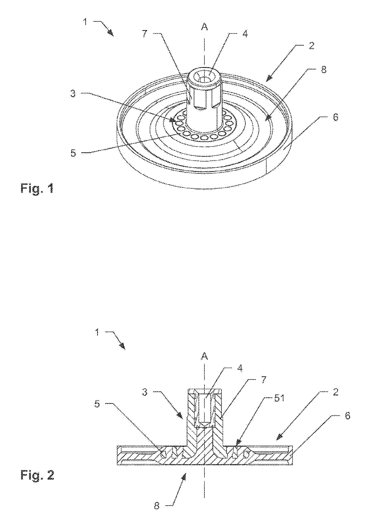
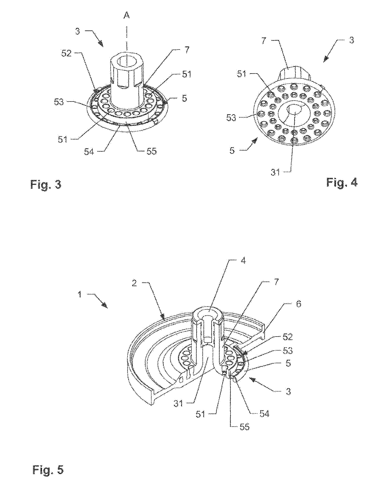
[0010]The pump diaphragm for a diaphragm pump for conveying a fluid comprises a solid core with a connection means for a drive rod of the diaphragm pump and a plate-shaped, elastic diaphragm body made of rubber with a peripheral clamping edge. The solid core is at least partially embedded in the diaphragm body. Furthermore, the solid core is produced from a thermoplastic and forms covalent bonds with the elastic diaphragm body made of rubber without adhesive.

[0011]That is to say that the thermoplastic and the rubber are selected such that, in the production of the pump diaphragm, they enter at their boundar...


PUM

PropertyMeasurementUnit
Metallic bondaaaaaaaaaa
Elasticityaaaaaaaaaa
Thermoplasticityaaaaaaaaaa

Abstract

A pump diaphragm for a diaphragm pump for conveying a fluid includes a solid core with a connection device for a drive rod of the diaphragm pump, and a plate-shaped elastic diaphragm body made of rubber having a peripheral clamping edge. The solid core is embedded at least partially in the diaphragm body and the solid core is produced from a thermoplastic and forms covalent bonds with the elastic diaphragm body made of rubber without adhesive. For this purpose, the thermoplastic, for example polyamide 612 or polyphenylene ether, and the rubber, a periodically cross-linked rubber such as EPDM, are selected in such a way that they are covalently cross-linked with one another at the boundary layer. In this way, a bonding layer that is susceptible to weakening or destruction is not present between the core and the diaphragm body.

Description

TECHNICAL FIELD[0001]The invention relates to a pump diaphragm, in particular a metering pump diaphragm, for a diaphragm pump for conveying a fluid.TECHNICAL BACKGROUND[0002]A diaphragm pump for conveying fluids comprises as an essential element a pump diaphragm, which comprises a circular functional region and a peripheral clamping edge surrounding the function region. It is fastened in the diaphragm pump by the clamping edge. The drive of the pump is separated by the pump diaphragm from the fluid in the pump chamber. In order to convey the fluid, the circular functional region of the pump diaphragm in the operating state is deflected or driven either hydraulically, pneumatically, mechanically or electromechanically essential along a longitudinal axis running through the centre of the functional region.[0003]Mechanically driven pump diaphragms typically comprise a flexible diaphragm body made of rubber and, partially embedded therein, a solid core with a connection means for the dr...

Claims


Application Information

Patent Timeline
IPC IPC(8): F04B43/02F04B43/00F04B15/02
CPCF04B43/021F04B43/0054F04B15/02F05C2225/02F05C2225/06F05C2225/08F04B43/02
Inventor DIEZ DIAZ, MARIA DEL MARRANDLER, RUDOLFKALIN, RAPHAELHABERLAND, NORBERT
Owner DATWYLER SCHWEIZ AG
Why Eureka
Try Eureka