Sensor diagnostics for a capacitive sensing system

a capacitive sensing and sensor technology, applied in the direction of pedestrian/occupant safety arrangements, transportation and packaging, vehicular safety arrangements, etc., can solve the problem of not being able to measure the voltage drop across the heater, the capacitive antenna electrode no longer correctly fulfills its function, and the solution of injecting dc cannot be used. problem, to achieve the effect of fast modification of method steps and robust and reliable execution of methods

Inactive Publication Date: 2019-08-29
IEE INT ELECTRONICS & ENG SA
View PDF0 Cites 1 Cited by
  • Summary
  • Abstract
  • Description
  • Claims
  • Application Information

AI Technical Summary

Benefits of technology

[0048]The software module can enable a robust and reliable execution of the method and can allow for a fast modification of method steps.

Problems solved by technology

If the electric heating member was interrupted, it would no longer correctly fulfil its function as capacitive antenna electrode.
If one or more additional heater(s), for example a back rest heater, is or are connected in parallel to the heater ECU, a simple solution which injects a DC current into the heaters and measures the voltage drop across the heaters is not possible because the paralleled back rest heater will hide a seat heater interruption.
Also other conventional methods for performing a functional test of the electric heating member cannot be applied.
For instance, an injection of an electric current of the usual high measurement frequencies through the electric heating member via the common mode choke is not feasible due to the required guarding.
Another conventional method, which is to control the heating current supply to provide a heating current pulse, is not a viable option as the heating current supply (or a control unit that is provided to control the heating current supply) may be in a low-voltage or fault mode, or a communication to the control unit may not be available at all times.

Method used


Image

  • Sensor diagnostics for a capacitive sensing system
  • Sensor diagnostics for a capacitive sensing system
  • Sensor diagnostics for a capacitive sensing system

Examples


Embodiment Construction

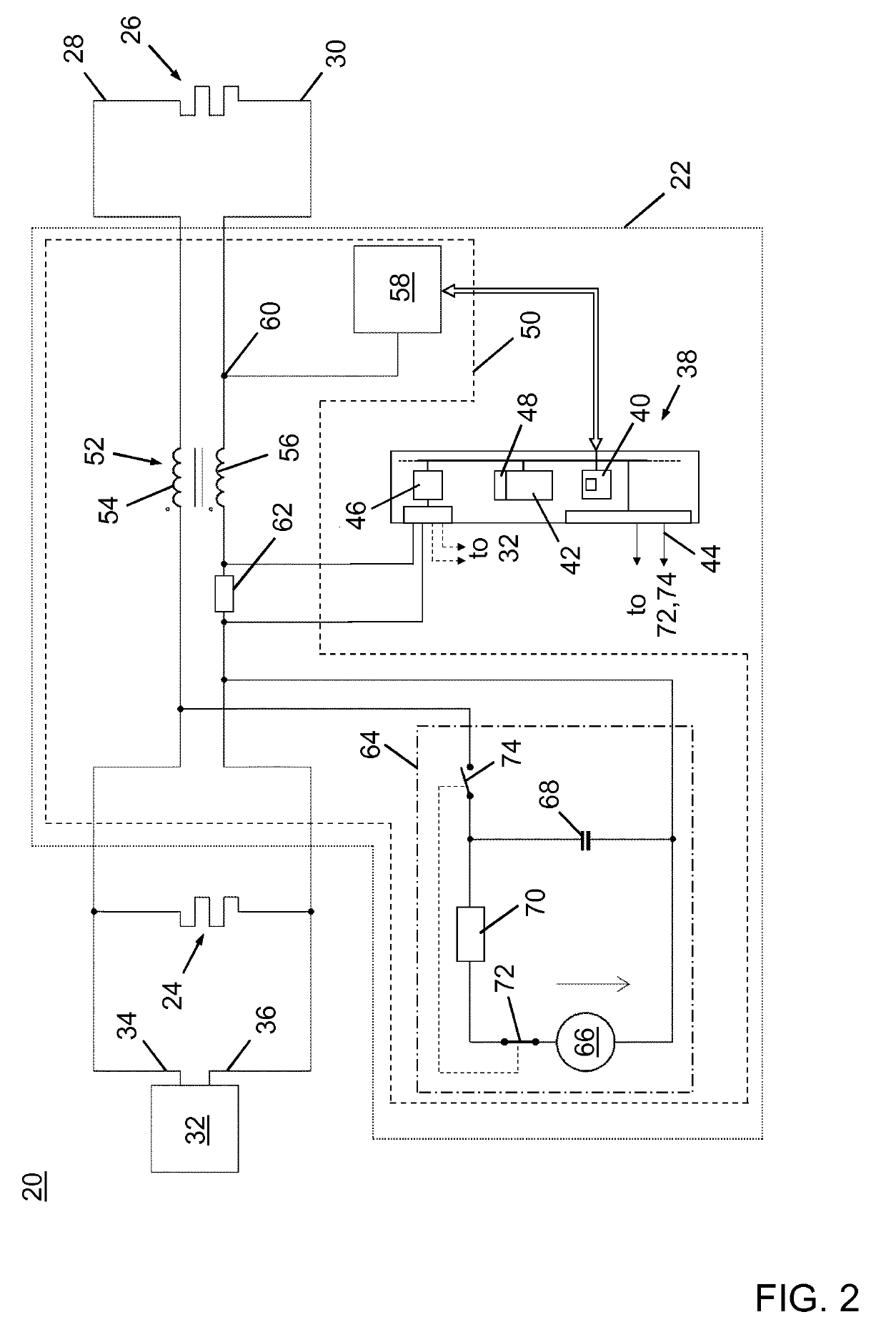
[0054]FIG. 2 illustrates a layout of an embodiment of a seat occupancy detection system 20 comprising a capacitive measurement system 22 with a capacitive sensor device 50 in accordance with the invention.

[0055]The seat occupancy detection system 20 is configured to detect an occupancy of a seat, in particular a vehicle seat of a passenger car, and includes the capacitive measurement system 22, a first electric heating member 24 that is arranged at a backrest of the vehicle seat and a second electric heating member 26 that is arranged at a seat cushion forming part of the vehicle seat. The second electric heating member 26 is employed as a capacitive antenna electrode. Moreover, the seat occupancy detection system 20 comprises a heating current supply 32 designed as an electronic control unit for providing electric power to the electric heating members 24, 26. In an operational state, the heating current supply 32 is configured to switch the electric power that is provided between a...


PUM


Abstract

A capacitive sensor device configured for being connected to at least one electric heating member serving as a capacitive antenna electrode. The capacitive sensor device includes a common mode choke connected between the heating current supply and the electric heating member, a capacitive sensing circuit configured to determine a complex electrical impedance between the electric heating member and a counter electrode, an electric measuring shunt for providing a voltage that is representative of an electric current flowing through the electric heating member, and a remotely controllable source of direct current electrically connected in parallel to the heating current supply. The remotely controllable source of direct current is configured to provide, upon receiving a remote control signal, an electric pulse having a predetermined amount of electric charge to the at least one electric heating member.

Description

TECHNICAL FIELD[0001]The present invention generally relates to capacitive sensing, e.g. for detecting the presence or absence of a person on a seat (seat occupancy detection) or the presence or absence of a person's hand on the steering wheel of a car (hands-off or hands-on detection).[0002]More specifically, the present invention relates to a capacitive sensor device using a heating member as an antenna electrode, and a seat occupancy detection system for detecting an occupancy status of the seat, in particular a vehicle seat, comprising such capacitive sensor device.BACKGROUND OF THE INVENTION[0003]Capacitive sensors and capacitive measurement and / or detection systems employing capacitive sensors have a wide range of applications, and are among others used for the detection of the presence and / or the position of a conductive body in the vicinity of an antenna electrode. As used herein, the term “capacitive sensor” designates a sensor, which generates a signal responsive to the in...

Claims


Application Information

Patent Timeline
Patent Type & Authority Applications(United States)
IPC IPC(8): B60N2/00B60R21/015B60N2/56
CPCB60N2/002B60R21/0154B60N2/5685B60R21/01532H01H2083/203H01H2083/201B60R16/037
Inventor LAMESCH, LAURENT
Owner IEE INT ELECTRONICS & ENG SA
Why Eureka
Try Eureka