Capacitive measurement circuit with offset compensation

a measurement circuit and offset compensation technology, applied in the field of measuring circuits, can solve problems such as inability to increase sensitivity, and achieve the effect of high flexibility in selecting discharging parameters

Active Publication Date: 2019-08-01
IEE INT ELECTRONICS & ENG SA
View PDF11 Cites 0 Cited by
  • Summary
  • Abstract
  • Description
  • Claims
  • Application Information

AI Technical Summary

Benefits of technology

[0023]In this way, an amount of electric charge can be transferred from the unknown capacitor to the integration capacitor that is substantially independent of the charging status of the integration capacitor. If the charge transfer circuit was not present in the proposed measurement circuit, such that the at least one electrically conductive electrode was directly electrically connected to the integration capacitor, the amount of transferred electric charge would decrease with each additional charge transfer cycle. Herein, a charge transfer cycle shall be defined as charging the unknown capacitor and subsequently electrically connecting the at least one electrically conductive electrode to the integration capacitor for transferring electric charge to the latter. A difference in voltage between a voltage of the unknown capacitor and a voltage of the integration capacitor would decrease with each additional charge transfer cycle, as the voltage of the integration capacitor increases over a measurement sequence including a plurality of charge transfer cycles. In fact, a sensitivity of the measurement circuit would decrease asymptotically to zero after a global maximum if the number of transfer cycles is increased. This means that the sensitivity could not be increased by increasing the number of charge transfer cycles. The measurement circuit in accordance with the invention eliminates this problem, enabling to increase the sensitivity of the measurement substantially proportionally to the number of charge transfer cycles.
[0063]The software module can enable a robust and reliable execution of the method and can allow for a fast modification of method steps.

Problems solved by technology

From a signal measurement technique point of view this means a challenge, as a required precision of measurement has to be maintained over a complete range of values that the capacitance offset might take on.
This means that the sensitivity could not be increased by increasing the number of charge transfer cycles.

Method used


Image

  • Capacitive measurement circuit with offset compensation
  • Capacitive measurement circuit with offset compensation
  • Capacitive measurement circuit with offset compensation

Examples


Embodiment Construction

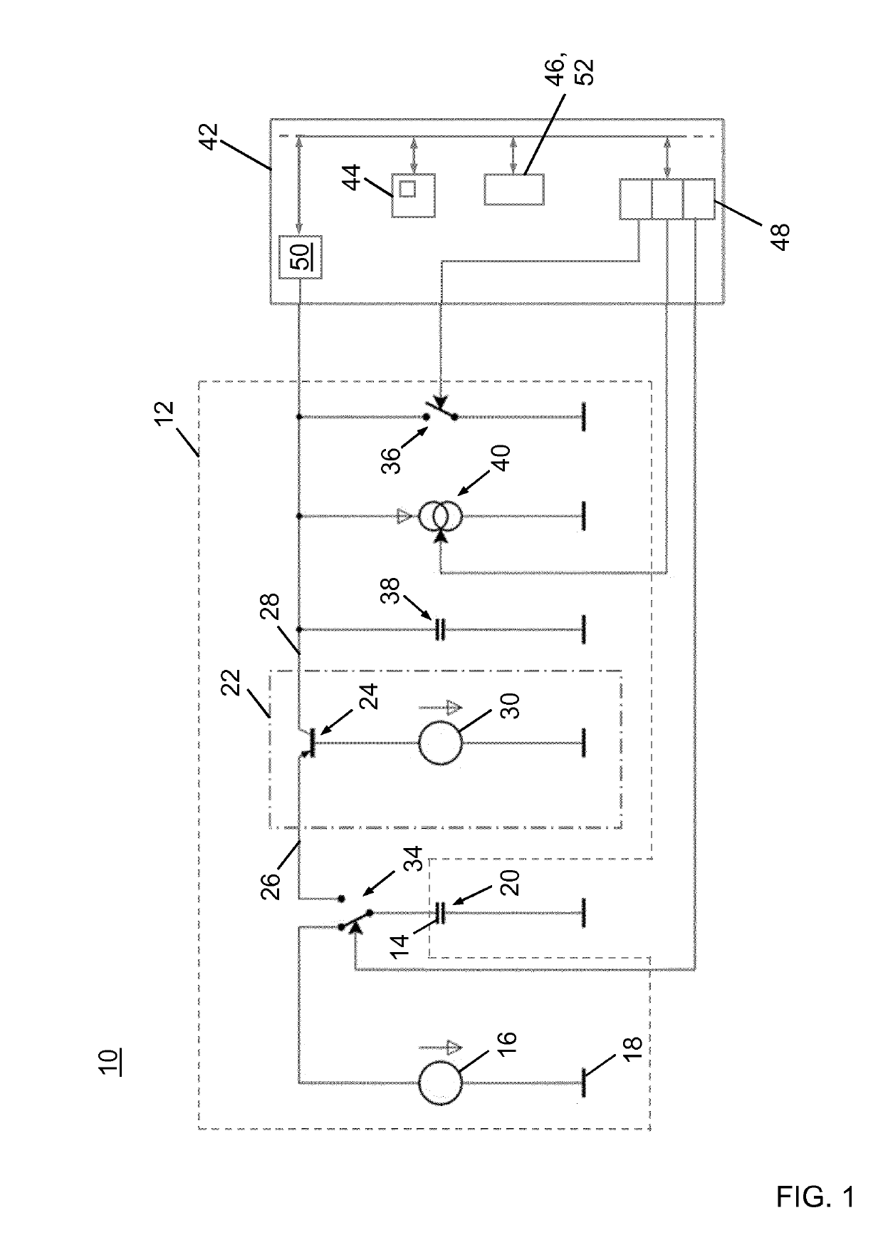
[0068]FIG. 1 schematically shows a layout of an embodiment of a capacitive measurement system 10. The capacitive measurement system 10 comprises a measurement circuit 12 in accordance with the invention, and an electrically conductive electrode 14 that is provided for forming a capacitor 20 in conjunction with a reference electrode, which capacitor 20 may be referred to as the “unknown capacitor”20 hereinafter. The capacitance of the unknown capacitor 20 is influenced by presence of an object or a living being in its vicinity. The capacitance may have an offset capacitance portion due to varying ambient and / or surrounding conditions of the unknown capacitor 20. In this specific embodiment, the reference electrode is formed by a vehicle chassis.

[0069]The measurement circuit 12 includes a direct current (DC) voltage source 16 for providing a charging voltage with reference to a ground potential 18 which is given by the electric potential of the reference electrode, a first switching m...


PUM


Abstract

A measurement circuit for a capacitive measurement system includes a DC voltage source, a first switching member, a charge transfer circuit, an integration capacitor and a current sink electrically connected in parallel to the integration capacitor. The charge transfer circuit has an active semiconductor device and a direct current bias voltage source. At least one electrically conductive electrode that forms a capacitor of unknown capacitance in conjunction with a reference electrode is electrically connectable either to the DC voltage source for charging or to the charge transfer circuit for discharging into the integration capacitor. The charge transfer circuit is configured for receiving an electric input current at an input port and for giving out an electric output current at an output port that is equal to the electric input current within a predetermined range of voltages across the input port and the output port of the charge transfer circuit.

Description

TECHNICAL FIELD[0001]The present invention generally relates to a measurement circuit for a capacitive measurement system, a capacitive measurement system comprising such measurement circuit and a method of operating such capacitive measurement system.BACKGROUND OF THE INVENTION[0002]Capacitive sensors and capacitive measurement systems employing capacitive sensors have a wide range of applications, and are among others used for the detection of the presence and / or the position of a conductive body in the vicinity of an electrically conductive electrode. As used herein, the term “capacitive sensor” designates a sensor, which generates a signal responsive to the influence of what is being sensed (a person, a part of a person's body, a pet, an object, etc.) upon an electric field. A capacitive sensor generally comprises at least one electrically conductive electrode at which the influence of an object or living being on the electric field of a capacitor formed by the at least one elec...

Claims


Application Information

Patent Timeline
Patent Type & Authority Applications(United States)
IPC IPC(8): G01R27/26H03K17/96H03M1/12
CPCG01R27/2605H03K17/962H03M1/12H03K2217/960725H03K17/955
Inventor LAMESCH, LAURENT
Owner IEE INT ELECTRONICS & ENG SA
Why Eureka
Try Eureka