Subsequent MRI configuration dependent eddy current compensation

Active Publication Date: 2019-01-24
KONINKLJIJKE PHILIPS NV
View PDF2 Cites 0 Cited by
  • Summary
  • Abstract
  • Description
  • Claims
  • Application Information

AI Technical Summary

Benefits of technology

[0024]Preferably, the at least one detection means is configured to determine at least one out of a position and an orientation of the additional device or the additional devices relative to the inner region, which can enable applying a dedicated eddy current correction that is specific not only to the additional device but also to a position and/or an orientation of the additional device, and, by that, facilitating a use of the additional device in different positions and/or orientations during MR imaging examination. Notably, the position and

Problems solved by technology

The time-varying magnetic fields intentionally generated by gradient coils of an MR imaging system can generate undesired eddy currents in electrically conductive

Method used


Image

  • Subsequent MRI configuration dependent eddy current compensation
  • Subsequent MRI configuration dependent eddy current compensation
  • Subsequent MRI configuration dependent eddy current compensation

Examples


Embodiment Construction

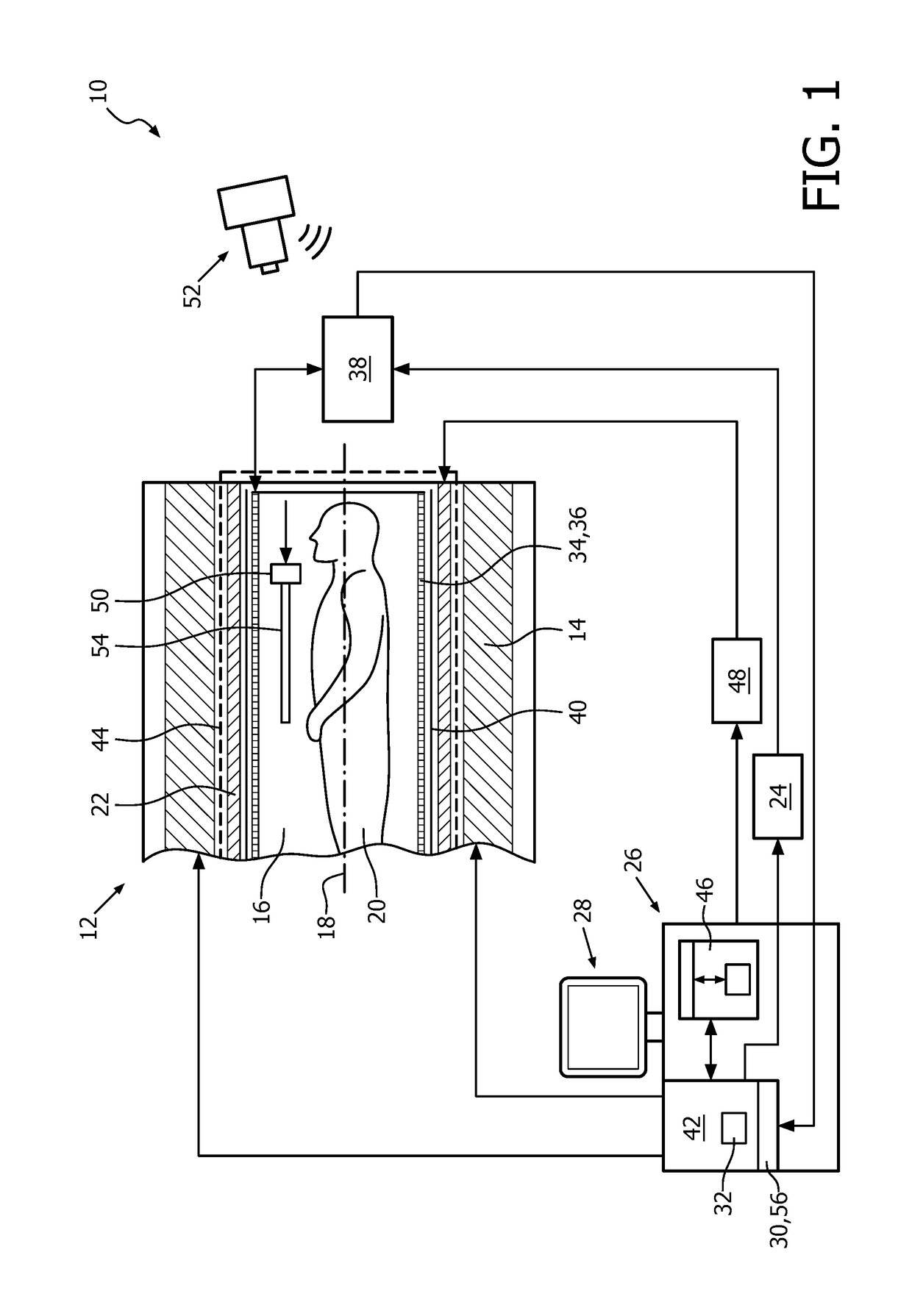
[0062]FIG. 1 shows a schematic illustration of a part of an embodiment of a magnetic resonance imaging system 10 in accordance with the invention. The magnetic resonance imaging system 10 is configured for acquiring magnetic resonance images from at least a portion of a subject of interest 20, usually a patient. The magnetic resonance imaging system 10 comprises a scanner unit 12 having a main magnet 14. The main magnet 14 has a central bore that provides an examination space 16 around a center axis 18 for the subject of interest 20 to be positioned within at least during examination, and is further configured for generating a static magnetic field B0 of appropriate magnetic field strength at least in the examination space 16. For clarity reasons, a customary table for supporting the subject of interest 20 is omitted in FIG. 1. The static magnetic field B0 defines an axial direction that is usually denoted as the direction of the z-axis of a Cartesian coordinate system and is aligne...


PUM


Abstract

A magnetic resonance imaging system (10) comprises a magnetic gradient coil system (22) configured for generating gradient magnetic fields by providing a predetermined temporal electrical current profile to at least one magnetic gradient coil in accordance with a desired magnetic resonance examination mode. An additional device (50), which is not part of the original magnetic resonance imaging system (10) as such, is intended to be positioned within an inner region (44) of the magnetic resonance imaging system (10) for special examination or other purposes. The additional device (50) is capable of generating an eddy current in at least a portion of the additional device (50) when being exposed to the generated gradient magnetic field. The magnetic resonance imaging system (10) is configured for modifying the predetermined electrical current profile at least on the basis of at least one predetermined parameter set upon receipt of an information indicative of a presence of at least one additional device (50) within an inner region (44) of the magnetic resonance imaging system (10); and—a method of operating a magnetic resonance imaging system (10) with regard to generating a gradient magnetic field by at least one magnetic gradient coil of a gradient coil system (22) in the presence of at least one additional device (50).

Description

FIELD OF THE INVENTION[0001]The invention pertains to a magnetic resonance imaging system with eddy current correction, and a method of operating the magnetic resonance imaging system with regard to generating a gradient magnetic field.BACKGROUND OF THE INVENTION[0002]In the field of magnetic resonance (MR) examination it is known that time-varying magnetic fields that are intentionally generated by gradient coils of an MR imaging system can generate undesired eddy currents in electrically conductive objects that are part of the MR imaging system.[0003]As one effect, the generated eddy currents themselves in turn generate magnetic fields that may cause serious problems in MR imaging and may result in image distortions, ghosting effects, unreliable water-fat separation, and may affect quantitative parameter evaluations such as q-flow. The eddy currents are therefore usually characterized and compensated for the MR imaging system, and at a limited field of view (FOV).[0004]For instanc...

Claims


Application Information

Patent Timeline
IPC IPC(8): G01R33/565G01R33/28G01R33/54
CPCG01R33/56518G01R33/283G01R33/543
Inventor VAN DEN BRINK, JOHAN SAMUEL
Owner KONINKLJIJKE PHILIPS NV
Why Eureka
Try Eureka