Bypass valve

a bypass valve and valve body technology, applied in multiple-way valves, mechanical equipment, chemistry equipment and processes, etc., can solve the problems of difficult operation, difficult to rotate the knob, adversely affecting the tight seal effect, etc., and achieves the effect of easy operation and new design

Inactive Publication Date: 2019-08-29
XIAMEN BAILIN WATER PURIFICATION TECH CO LTD
View PDF0 Cites 5 Cited by
  • Summary
  • Abstract
  • Description
  • Claims
  • Application Information

AI Technical Summary

Benefits of technology

[0006]In view of the problems and drawbacks of the prior art, the present invention provides a bypass valve, that is novel in design, and easy in operation.
[0010]Compared with the Prior Art, the bypass valve of the present invention has the following advantages: firstly, in achieving switching, it requires only to pull the mandrel out once, so that its operation is simple and easy. Secondly, the bypass pump is capable of performing mixed water regulations. And thirdly, the design of the bypass pump utilizes a 90 degree configuration, to save the space occupied.

Problems solved by technology

The deficiency of this structure is that, when rotating the mandrels in the receiving chamber, the tight seal ring is liable to be scratched and damaged by the rim of the opening of the receiving chamber, to adversely affect tight seal effect, hereby leading to function failure.
The drawback of this approach is that, to achieve water route switching, it requires to rotate the knob many turns.
Therefore, it is rather time consuming, and not convenient to operate; while its structure is complicated, and its stability is insufficient.
Therefore, presently, the design and performance of the bypass valve is not quite satisfactory, and it leaves much room for improvements.

Method used


Image

  • Bypass valve
  • Bypass valve
  • Bypass valve

Examples


Embodiment Construction

[0018]The purpose, construction, features, functions and advantages of the present invention can be appreciated and understood more thoroughly through the following detailed descriptions with reference to the attached drawings.

[0019]In the following, an embodiment is used to describe the various details of the present invention. However, it does not mean that this embodiment represents all the embodiments of the present invention. Other embodiments can be envisaged by people familiar with this field, and thus they all fall into the scope of the present invention.

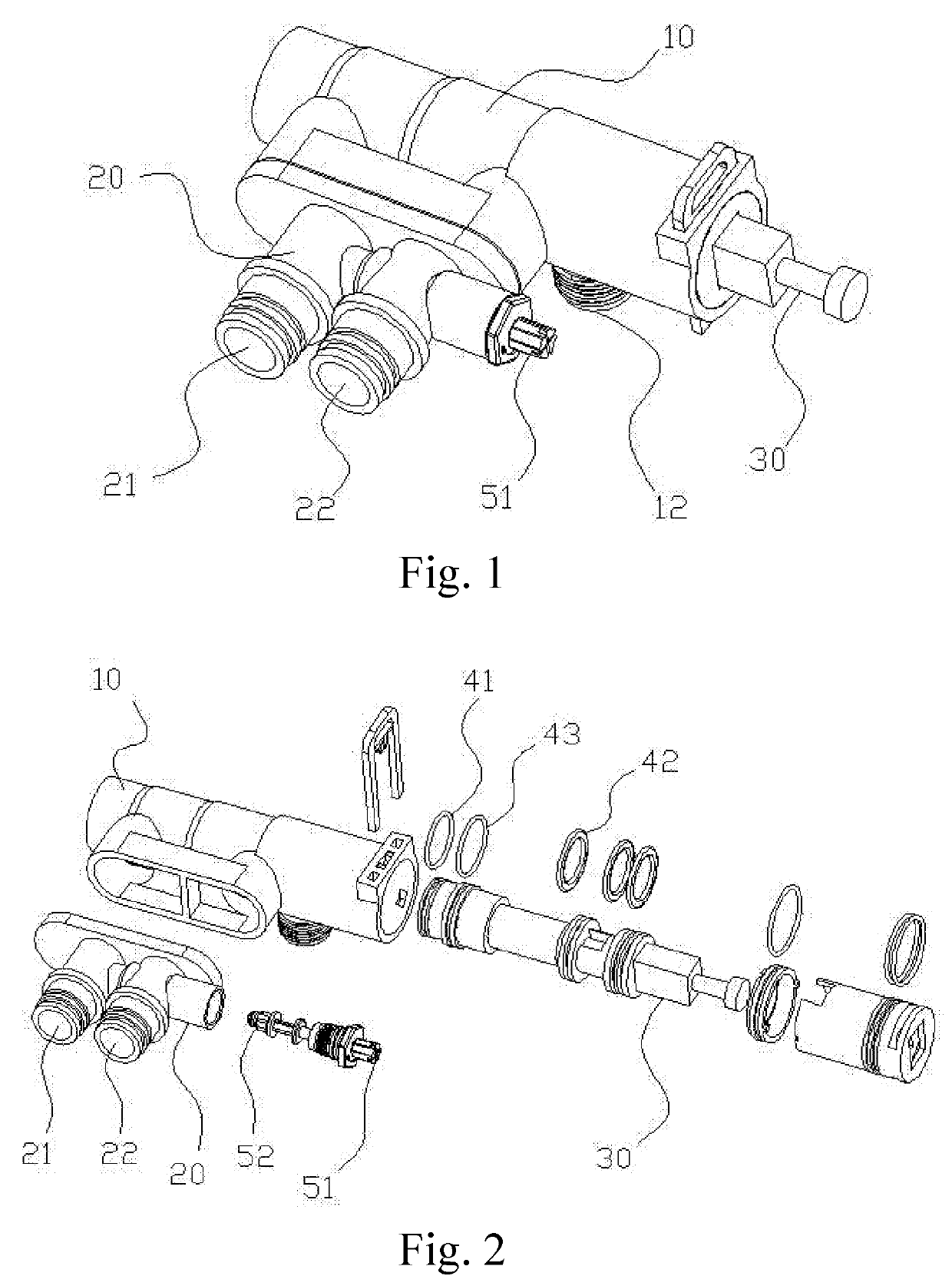
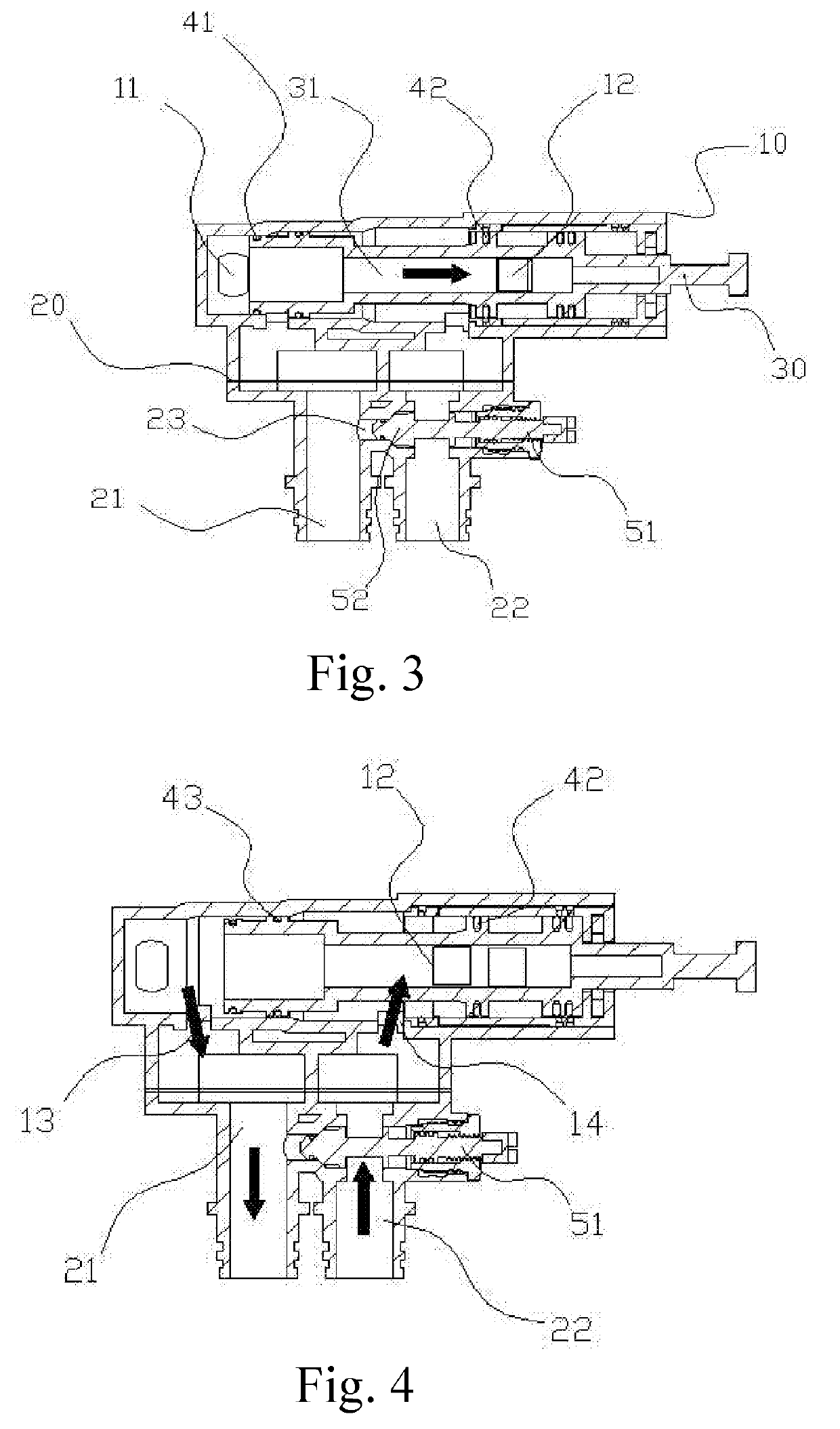
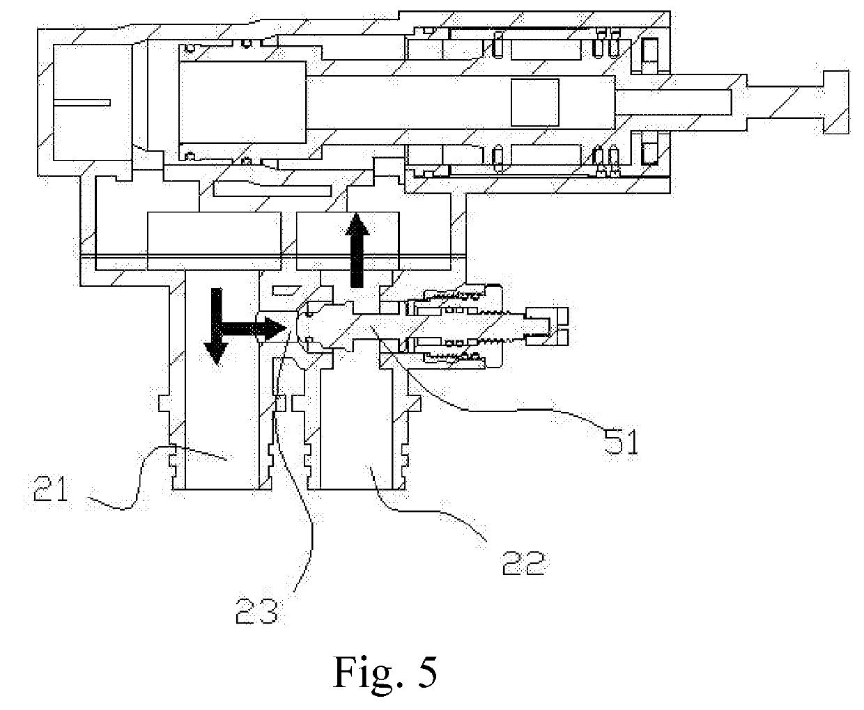
[0020]Refer to FIGS. 1-5 respectively for a perspective view of a bypass valve according to the present invention; an exploded view of a bypass valve according to the present invention; a schematic diagram of a bypass valve in a first condition according to the present invention; a schematic diagram of a bypass valve in a second condition according to the present invention; and a schematic diagram of a bypass valve in a thir...


PUM


Abstract

A bypass valve includes a first main body, with its two ends disposed a water inlet port and a water outlet port respectively. A mandrel capable of moving laterally is disposed in the first main body, and a water passage channel is disposed in the mandrel, for connecting and communicating the water inlet port with the water outlet port. A second main body is disposed below the first main body. In the second main body is disposed a water inlet channel and a water outlet channel, a first water passage hole is disposed between the water outlet channel and the water inlet port, and a second water passage hole is disposed between the water inlet channel and the water outlet port. The bypass valve is simple in construction, and is capable of achieving multi water routes switching.

Description

BACKGROUND OF THE INVENTIONField of the Invention[0001]The present invention relates to a valve, and in particular to a bypass valve.The Prior Arts[0002]Presently, the existing bypass valve structure uses mainly two approaches of switching.[0003]1. Utilizing two mandrels to rotate in a receiving chamber to change water route. The deficiency of this structure is that, when rotating the mandrels in the receiving chamber, the tight seal ring is liable to be scratched and damaged by the rim of the opening of the receiving chamber, to adversely affect tight seal effect, hereby leading to function failure.[0004]2. Adopting a side spiral approach, to control movement of valve cartridge. The drawback of this approach is that, to achieve water route switching, it requires to rotate the knob many turns. Therefore, it is rather time consuming, and not convenient to operate; while its structure is complicated, and its stability is insufficient.[0005]Therefore, presently, the design and performa...

Claims


Application Information

Patent Timeline
Patent Type & Authority Applications(United States)
IPC IPC(8): F16K11/04
CPCF16K11/04C02F2201/005C02F2301/043F16K11/0716
Inventor ZHAN, FENG-SHUN
Owner XIAMEN BAILIN WATER PURIFICATION TECH CO LTD
Why Eureka
Try Eureka