Terminal device, base station device, and method for controlling QOS

Active Publication Date: 2019-08-29
SK TELECOM CO LTD
View PDF3 Cites 8 Cited by
  • Summary
  • Abstract
  • Description
  • Claims
  • Application Information

AI Technical Summary

Benefits of technology

[0032]According to the terminal apparatus and the BS apparatus according to the present disclosure, it is possible to derive effects of applying differential QoS, that is, service qualities to respective communication services by enabling the service flow-based QoS control without an increase in complexity compared to the

Problems solved by technology

However, the limit may be a problem which should be solved in a current or future situation (

Method used


Image

  • Terminal device, base station device, and method for controlling QOS
  • Terminal device, base station device, and method for controlling QOS
  • Terminal device, base station device, and method for controlling QOS

Examples


Example

[0040]The QoS control method proposed by the present disclosure may derive the following effects.

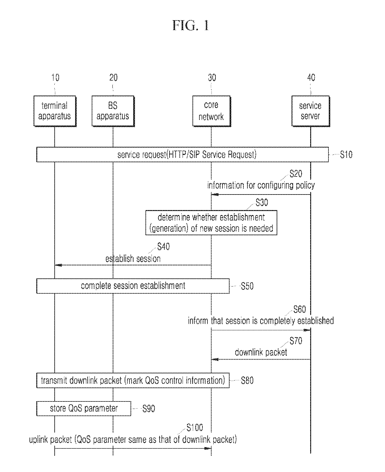
[0041]That is, according to the present disclosure, there are noticeable effects in that application services having different service requirements can receive different QoS by controlling the QoS based on the service flow instead of the conventional bearer and in that control signaling can be minimized through a reflective QoS control method of applying, to an uplink, the same QoS parameter applied to a downlink when the service flow-based QoS control is implemented.

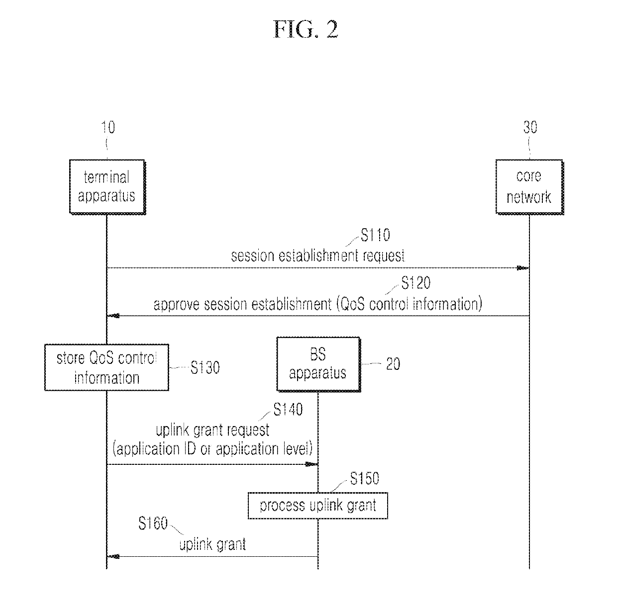
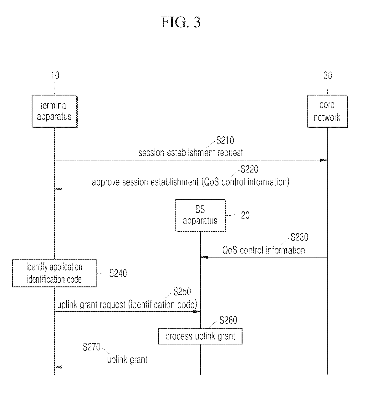
[0042]Further, according to the present disclosure, there are noticeable effects in that a response time of a service request can be improved by realizing a QoS control for an uplink corresponding to an initial service request, which has not been available to QoS control, and in that resource use efficiency can be maximized and exposure of a QoS control policy to the outside can be prevented by replacing application identifi...


PUM


Abstract

Disclosed are a terminal apparatus, a BS apparatus, and a QoS control method for realizing a service flow-based QoS control without an increase in complexity compared to the conventional bearer-based QoS control method and improving a response time of a service request by making a QoS control for an initial service flow generated according to the service request possible.

Description

CROSS-REFERENCE TO RELATED APPLICATIONS[0001]The present application is a continuation of International Application No. PCT / KR2017 / 002185 filed on Feb. 28, 2017, which is based on, and claims priority from, Korean Patent Application No. 10-2016-0140161, filed on Oct. 26, 2016, the entire contents of which are incorporated herein by reference.BACKGROUND OF THE INVENTION1. Field of the Invention[0002]The present disclosure relates to a method of realizing a service flow-based QoS control without an increase in complexity compared to a conventional bearer-based QoS control method and enabling a QoS control for an initial service flow generated according to a service request to improve a response time of the service request.2. Description of the Prior Art[0003]In a mobile communication system, a Quality of Service (QoS) level varies depending on the media type of application service used by a terminal apparatus (user), and a QoS control for transmitting a packet of the application servi...

Claims


Application Information

Patent Timeline
IPC IPC(8): H04W28/02H04W72/14
CPCH04W72/14H04W28/0268H04W76/11H04W76/22H04W28/0992H04W72/566H04W72/21H04W28/06H04W72/569H04W72/23H04W28/02H04W72/12
Inventor JEONG, SANG SOOPARK, JONG HAN
Owner SK TELECOM CO LTD
Why Eureka
Try Eureka