Power management for solid state drives in a network

a solid-state drive and network technology, applied in the direction of power supply for data processing, input/output to record carriers, instruments, etc., can solve the problems of occupying significant rack space for ssds, occupying enclosures themselves significant real estate, and traditional host hdd interfaces are not capable of taking full advantage of ssd performance, etc., to achieve the effect of managing the power consumption

Active Publication Date: 2019-09-12
TOSHIBA MEMORY CORP
View PDF2 Cites 4 Cited by
  • Summary
  • Abstract
  • Description
  • Claims
  • Application Information

AI Technical Summary

Benefits of technology

[0016]In one embodiment, a method of implementing a plurality of SSDs over a network includes, identifying a total system power, allocating a power level to each of a plurality of SSDs communicatively coupled to a plurality of powered ports of a switch, and managing the power consumed by each of the plurality SSDs by limiting performance of write commands by each of the plurality of SSDs based on the allocated power level to each of the plurality of SSDs. The total of the allocated power does not exceed the total system power.

Problems solved by technology

Although the development of fast media has enabled the use of SSDs in NVMeoF implementations, the existing disk packaging for SSDs occupy significant server rack space.
With the development of smaller form factor SSDs, more SSDs can be incorporated within a given server rack mount enclosure, however, the enclosures themselves occupy significant real estate that could otherwise be used by other devices.
Additionally, a traditional host HDD interface is not capable of taking full advantage of the performance of a SSD.
For example, the host client using an HDD interface is not capable of issuing low-level commands that govern how data is programmed and erased in the SSD and the SSD is not aware of when the host client will issue read or write commands.
Accordingly, both the SSD controller and the host client employ best effort approaches for performing their independent functions, which results in inefficient utilization of SSD resources, including, for example, imbalanced distribution of load and power consumption among SSD devices, inefficient use of volatile memory capacity, unpredictable data storage, and increased wear-leveling of SSD memory.

Method used


Image

  • Power management for solid state drives in a network
  • Power management for solid state drives in a network
  • Power management for solid state drives in a network

Examples


Embodiment Construction

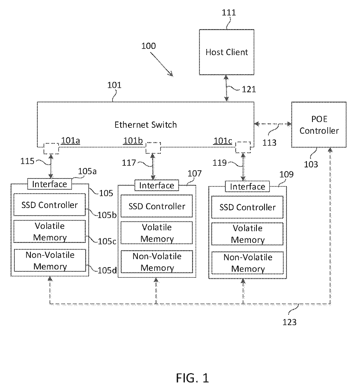
[0022]FIG. 1 is a block diagram illustrating one embodiment of SSDs in a network 100. An Ethernet switch 101 communicates with a POE controller 103 over connection 113, a plurality of SSDs 105, 107, and 109 over connections 115, 117, and 119 respectively, and a host client 111 over connection 121. The host client 111 may communicate with the Ethernet switch 101 using a standard Ethernet port, or any known method in the art, including, but not limited to, a PCIE port, and / or a UART port (among others). In one embodiment, any number of host clients 111 may communicate with Ethernet switch 101. The Ethernet switch 101 includes a plurality of Ethernet ports, 101a, 101b, and 101c that can be used to connect one or more Ethernet devices. In one embodiment, Ethernet switch 101 is capable of providing power to a device connected to each of the available Ethernet ports 101a, 101b, and 101c (i.e., “power over Ethernet” or “POE”). In one embodiment, one or more of the available Ethernet ports ...


PUM


Abstract

In one embodiment, a network of SSDs includes a switch with a plurality of powered ports configured to be communicatively coupled to a controller and a host client and a plurality of SSDs configured to be communicatively coupled to the plurality of powered ports. The switch is configured to deliver up to a predefined power level to each of the plurality of SSDs via the plurality of powered port. Each of the plurality of SSDs consumes power. The controller is configured to manage the predefined power level for each of the plurality of SSDs by identifying the power consumed by each of the plurality of SSDs and allocating a new power level to each of the plurality of SSDs based on the power consumed by each of the plurality of SSD. In one embodiment, the switch and the plurality of SSDs are configured to occupy a server rack space.

Description

FIELD OF THE INVENTION[0001]This invention generally relates to an implementation of solid state drive (SSDs) in a network that enables efficient management of power.BACKGROUND OF THE INVENTION[0002]A typical SSD includes non-volatile NAND media (comprised of memory blocks capable of retaining data when disconnected from power), a controller and a host interface (e.g., PCIe, SAS, SATA, or any other interface compatible with hard disk drives (HDD)) to receive commands from a host client computer. The SSD controller translates logical addresses used in commands transferred across a host interface (e.g., logical read and write commands from a host client computer sent across the host interface to the SSD) to low-level flash operations (e.g., read, program, and erase) for the associated physical block and page addresses of the SSD. The SSD controller also performs numerous other functions, including, for example: error code correction; garbage collection; scheduling; managing over-provi...

Claims


Application Information

Patent Timeline
Patent Type & Authority Applications(United States)
IPC IPC(8): G06F3/06G06F1/32
CPCG06F3/0634G06F3/0625G06F1/3268G06F3/0688G06F1/3225
Inventor KLEIN, YARON
Owner TOSHIBA MEMORY CORP
Why Eureka
Try Eureka