
Smart card with reconfigurable receiver

a receiver and smart card technology, applied in the field of smart cards with reconfigurable receivers, can solve the problems of increasing power consumption at the transmitting side, other non-idealities affecting the received signal, gain misajustement, etc., and achieve the effect of avoiding a long preamble for calibration purposes

Active Publication Date: 2015-05-26
NXP BV
View PDF17 Cites 2 Cited by
  • Summary
  • Abstract
  • Description
  • Claims
  • Application Information

AI Technical Summary

Benefits of technology

[0009]According to an aspect of the invention the digital signal processing receiver is further arranged to reconfigure itself in dependence on the quality of the signal received from the reader unit, in order to minimize its power consumption. In short, a certain amount of training can be dispensed with if the quality of the signal is high enough. This is a convenient way to manage the power consumption of the smart card.
[0011]According to a further aspect of the invention the digital signal processing receiver is further arranged to determine whether the reader unit will transmit either a first preamble only, said first preamble comprising a basic training sequence for calibrating one or more signal parameters, or both said first preamble and a second preamble, said second preamble comprising an additional training sequence for calibrating said signal parameters, wherein the digital signal processing receiver concludes that both said first preamble and said second preamble will be transmitted if the error vector magnitude is above a predetermined threshold. This implementation has the advantage that a long preamble for calibration purposes can be avoided in cases where the power budget of the reader unit allows for a high-quality signal.

Problems solved by technology

On top of ISI, other non-idealities affect the received signal, such as DC offset, gain misadjustment and timing offsets.
For example, the base station typically provides a clear signal which increases the power consumption at the transmitting side.
However, in case of a reader unit comprised in an NFC-enabled mobile device, the available power is limited and therefore the transmitted signal is less clear.
In this case the digital signal processing which takes place at the receiving side is relatively complex and the required preamble is relatively long.
Therefore, the DSP receiver is not very flexible, and the smart card on which it is integrated is limited in its use.

Method used


Image

  • Smart card with reconfigurable receiver
  • Smart card with reconfigurable receiver
  • Smart card with reconfigurable receiver

Examples


Embodiment Construction

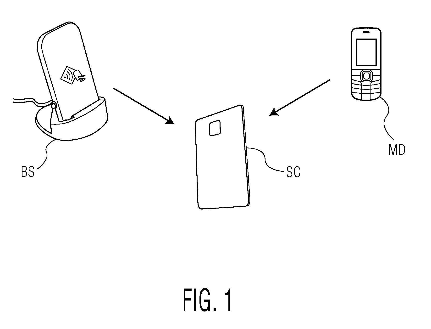
[0022]FIG. 1 shows a smart card SC which communicates either with a reader unit BS connected to a power supply net or with a reader unit MD comprised in an NFC-enabled mobile device. As explained above, the power requirements of reader units are completely different depending on the application domain. The digital signal processing receiver comprised in the smart card according to the invention is arranged to determine the quality of a signal received from the reader unit by determining the error vector magnitude of this signal. Techniques for determining the error vector magnitude of a signal are known as such.

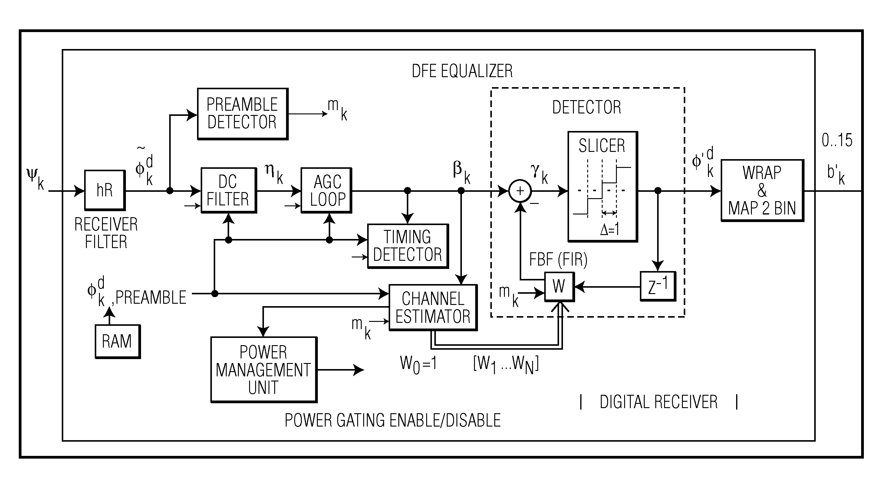
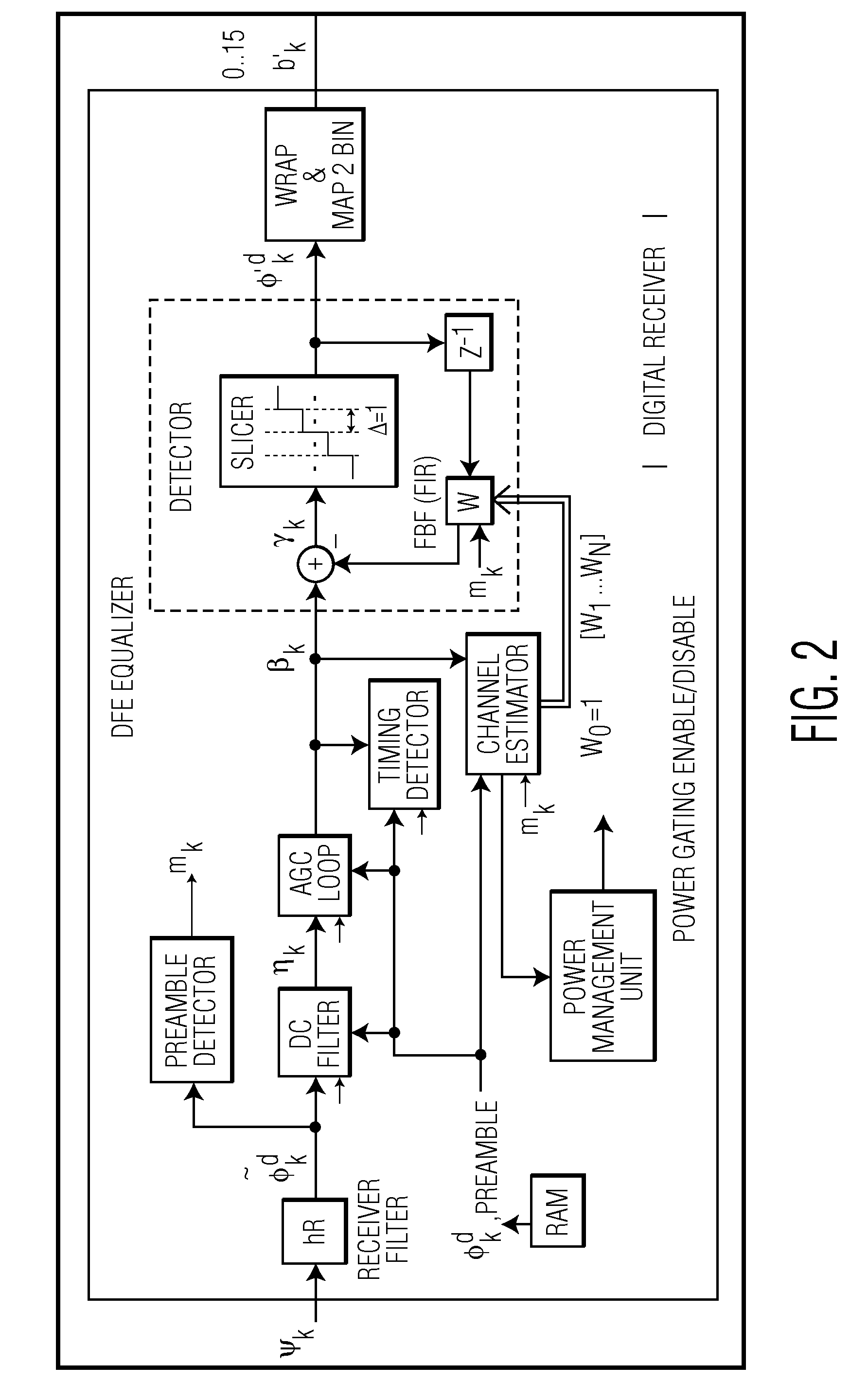
[0023]FIG. 2 shows an example of a digital signal processing receiver according to the invention. In operation, the digital signal processing receiver uses commonly employed front-end circuits to calibrate signal parameters such as DC, gain and timing. This is achieved during a first preamble which comprises a basic training sequence for calibrating the signal parameters. In ...


PUM


Abstract

The invention proposes a smart card which comprises a digital signal processing receiver that can automatically identify the type of a smart card reader based on the error vector magnitude of signals received from the reader. The digital signal processing receiver is able to reconfigure itself at runtime in order to optimally minimize its power consumption in dependence on the type of reader it is communicating with. Furthermore, the invention proposes a new preamble structure that comprises a basic part and an optional additional part.

Description

[0001]This application claims the priority under 35 U.S.C. §119 of European patent application no. 10186503.8, filed on Oct. 5, 2010, the contents of which are incorporated by reference herein.BACKGROUND OF THE INVENTION[0002]VHDR (Very High Data Rate) enabled smart cards are more and more positioned as the next generation of smart cards. New communication protocols between smart cards and smart card readers require a data rate of 1.7 Mb / s up to 13.56 Mb / s while the conventional carrier frequency of 13.56 MHz is still being used. This implies a high increase of Inter Symbol Interferences (ISI). ISI's corrupt the received waveform by interference which depends on the past transmitted symbols. As a result the present symbol is corrupted by the adjacent symbols. Equalization attempts to compensate ISI. On top of ISI, other non-idealities affect the received signal, such as DC offset, gain misadjustment and timing offsets. DC offset occurs when the mean value of the waveform is non-zero...

Claims


Application Information

Patent Timeline
Patent Type & Authority Patents(United States)
IPC IPC(8): G06K19/07H04W4/80
CPCG06K19/07G06K19/0723H04W4/80Y02D30/70H04L1/0053H04L1/0075H04L1/20
Inventor AL-KADI, GHIATHCIACCI, MASSIMOVAN DE BEEK, REMCO CORNELIS HERMAN
Owner NXP BV
Learn More