[0014]The present invention is directed toward addressing this need by providing a novel adjustable hinge assembly component. This adjustable hinge assembly component (adjustable hinge) may be installed and used in a sneeze guard in a manner which allows each of the transparent sneeze guard panes in a series of sneeze guard panes to be adjusted angularly and / or rotationally, within the need to tighten a screw or nut to lock the pane in a particular configuration.
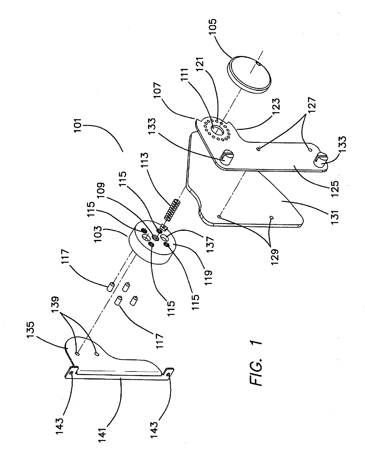
[0022]Preferably, the interior of each of these axial cavities is tapped in a manner complementary to the threads of a single retaining screw. The axial cavity in the inside surface of the second retaining plate is surrounded by a ring-like shoulder having a circumference sized to permit the shoulder to be received by the large axial hole of the rotatable arm in a manner permitting the arm to rotate freely around the shoulder. The shoulder has a height greater than the thickness of the rotatable arm, so that when the shoulder of the second retaining plate makes contact with the inside surface of the first retaining plate, the rotatable arm is free to rotate around the shoulder. Thus, when assembled, the shoulder serves as an axle around which the rotatable arm can rotate.
[0027]The plurality of ball pins of the first retaining plate and the plurality of detent holes of the rotatable arm are respectively aligned and arranged to provide various rotational “stop” positions at which the rotatable arm is held as it is moved with respect to the first retaining plate, wherein the balls of the ball pins engage with the detent holes and the rotatable arm is firmly, but movably, held in place by the ball pins. The springs of the ball pins permit the rotatable arm (or a component affixed thereto) to be rotated between stop positions by hand, thus compressing the balls of the ball pins as the detent holes move to another position. When the rotatable arm is moved sufficiently to permit the ball pins to engage a new set of detent holes, the springs of the ball pins cause the balls to again expand into the detent holes, thereby locking the rotatable arm in a new rotational position.
[0029]The plurality of ball pins may be any number greater than one, up to the number of detent holes. Preferably, the first retaining plate has at least three, or at least four ball pins, so that the rotatable arm is held firmly by each ball pin at each stop position. Also, preferably the ball pins are arranged in a manner than provide maximum physical stability to the rotatable am when its detent holes are engaged with the ball pins. Thus, if three ball pins are used, the ball pins are preferably arranged in a triangular pattern on the inside surface of the first retaining plate, and to simultaneously align with and engage with detent holes in the rotatable arm. If four pins are used, the ball pins are preferably arranged in a rectangular pattern on the inside surface of the first retaining plate. If five pins are used, the ball pins are preferably arranged in a pentagonal pattern on the inside surface of the first retaining plate, and so forth. Preferably, in all cases the ball pins ail simultaneously align and engage with detent holes in the rotatable arm.
[0053]When a sufficient strong force is applied to the rotatable arm, the am moves from a first locked angular position. By “locked position” or “locked angle” is meant a position at which ball pins and detent holes align and are engaged such that a sufficiently strong force is required to disengage them. As the rotatable arm moves, the ball pins of the first retaining plate are dislodged from the detent holes in the arm, and the amount of force required to continue rotation of the arm is greatly reduced until the arm reaches a new rotational angle at which the detent holes align with the ball pins of the first retaining plate. At this new locked rotational angle the ball pins again engage the detent holes and are dislodged only when a sufficiently strong force is again applied to the rotatable arm.

