Vehicular power transmitting system

Active Publication Date: 2019-09-19
TOYOTA JIDOSHA KK +1
View PDF11 Cites 2 Cited by
  • Summary
  • Abstract
  • Description
  • Claims
  • Application Information

AI Technical Summary

Benefits of technology

The present invention provides a vehicular power transmitting system with first and second oil strainers that make it easier to design the system. The system includes an oil reservoir that ensures stable oil levels, reducing the risk of air suction, and the oil pump does not need to be positioned high in the vehicle, reducing the risk of oil shortage. Additionally, the system has a space between the engine drive shaft and the differential shaft, which reduces the risk of air suction by the oil pump and allows for a shorter suction conduit. Overall, the power transmitting system is designed to have improved efficiency and stability.

Problems solved by technology

By the way, it is difficult to dispose the first and second oil strainers near an axis of an electric motor such that the two oil strainers are spaced apart from each other in the longitudinal direction of the vehicle, where the electric motor and a parking lock mechanism of the vehicular power transmitting system are large-sized according to a demand for increasing the capacity of the vehicular power transmitting system.
Further, where the oil strainers are disposed below the parking lock mechanism, there is a restriction of design regarding the positions of installation of the oil strainers.
This requirement makes it difficult to suitably design the arrangement of the vehicular power transmitting system.

Method used


Image

  • Vehicular power transmitting system
  • Vehicular power transmitting system
  • Vehicular power transmitting system

Examples


Embodiment Construction

[0024]In the present specification, descriptions of positions of various elements of a power transmitting system of a vehicle are based on an assumption that the vehicle lies on a level surface of a ground or roadway parallel to a horizontal plane. It is to be further understood that an “upward direction” and a “downward direction” described in the specification are perpendicular to the horizontal plane, and an “upper portion” and a “lower portion” described in the specification are the upper and lower portions as seen in a vertical plane perpendicular to the horizontal plane.

[0025]A preferred embodiment of the present invention will be described in detail by reference to the drawings. It is to be understood that the drawings showing the embodiment are simplified or transformed as needed, and do not necessarily accurately represent dimensions and shapes of various elements of the embodiment.

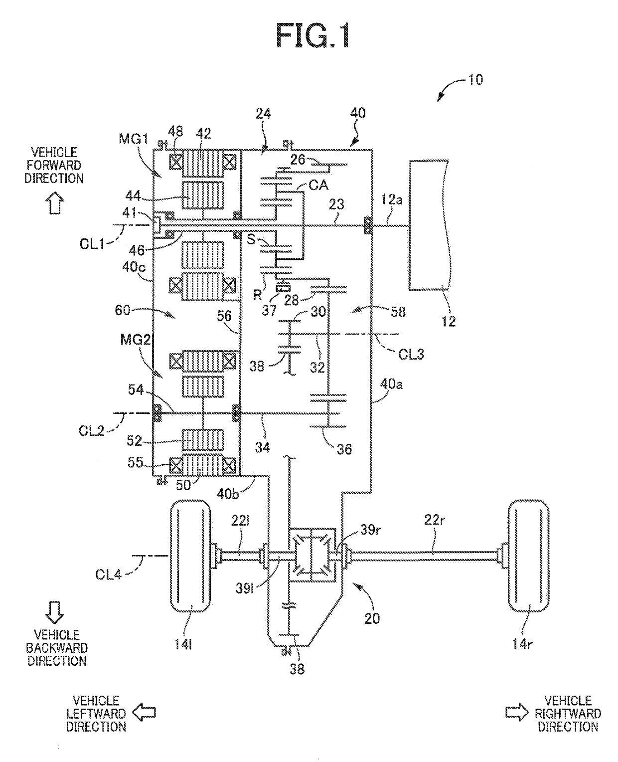
[0026]Reference is first made to FIG. 1, which is the schematic view of a power transmitting ...


PUM


Abstract

In a power transmitting system of a vehicle including a differential gear device including a differential shaft; a first oil pump; a first oil strainer connected to the first oil pump; a second oil pump; a second oil strainer connected to the second oil pump; and a casing within which the engine drive shaft, the differential gear device, the first and second oil pumps, and the first and second oil strainers are accommodated, such that the engine drive shaft and the differential shaft of the differential gear device are spaced apart from each other in a longitudinal direction of the vehicle, the first and the second oil strainers are disposed between the engine drive shaft and the differential shaft of the differential gear device in the longitudinal direction of the vehicle, and are spaced apart from each other in an axial direction of the engine drive shaft.

Description

[0001]This application claims priority from Japanese Patent Application No. 2018-049848 filed on Mar. 16, 2018, the disclosure of which is herein incorporated by reference in its entirety.FIELD OF THE INVENTION[0002]The present invention relates to an arrangement of a lubricating device provided in a vehicular power transmitting system.BACKGROUND OF THE INVENTION[0003]There is known a power transmitting system of a vehicle, which includes a first oil strainer connected to a first oil pump, and a second oil strainer connected to a second to a second oil pump. JP2017-136964A discloses an example of this type of power transmitting system, wherein an oil strainer connected to an oil pump operated by a differential gear device, and an oil strainer connected to an oil pump operated by an engine are spaced apart from each other in a longitudinal direction of the vehicle. WO2015 / 046592 also discloses a vehicular power transmitting system including two oil pumps, and two oil strainers connec...

Claims


Application Information

Patent Timeline
IPC IPC(8): F16H57/04
CPCF16H57/0476F16H57/0404F16H57/0483F16H57/045B60Y2200/92F16H57/0457F16H57/0436F16H57/0439F16H57/0482F16H57/04
Inventor IKEDA, AKIHIKOSUGIYAMA, MASATAKASUZUKI, TOMOAKIKATO, HIROSHIMIYANAGA, SATOSHIASAI, KENJI
Owner TOYOTA JIDOSHA KK
Why Eureka
Try Eureka