Deployable radiator

Active Publication Date: 2019-10-31
MITSUBISHI ELECTRIC CORP
View PDF0 Cites 2 Cited by
  • Summary
  • Abstract
  • Description
  • Claims
  • Application Information

AI Technical Summary

Benefits of technology

[0019]In the deployable radiator according to the present invention, the first radiator panel is connected to the body structure of the satellite by the first deployment mechanism. The first deployment mechanism deploys the first radiator panel from the state where the first radiator panel is opposed to the north or south face of the body structure of the satellite. The second radiator panel is stacked with the first radiator panel to be opposed to the north or south face of the body structure of the satellite and is sandwiched between the body structure of the satellite and the first radiator panel, in the state where the first radiator panel is opposed to the north or south face of the body structure of the satellite. The second deployment mechanism connects the second radiator panel to the body structure of the satellite and deploys the

Problems solved by technology

In recent years, due to larger power consumption of an artificial satellite, an amount of heat removal from the satellite has steadily been increasing.
A heat removal area becomes

Method used


Image

  • Deployable radiator
  • Deployable radiator
  • Deployable radiator

Examples


Example

First Embodiment

[0029]***Description of Configuration***

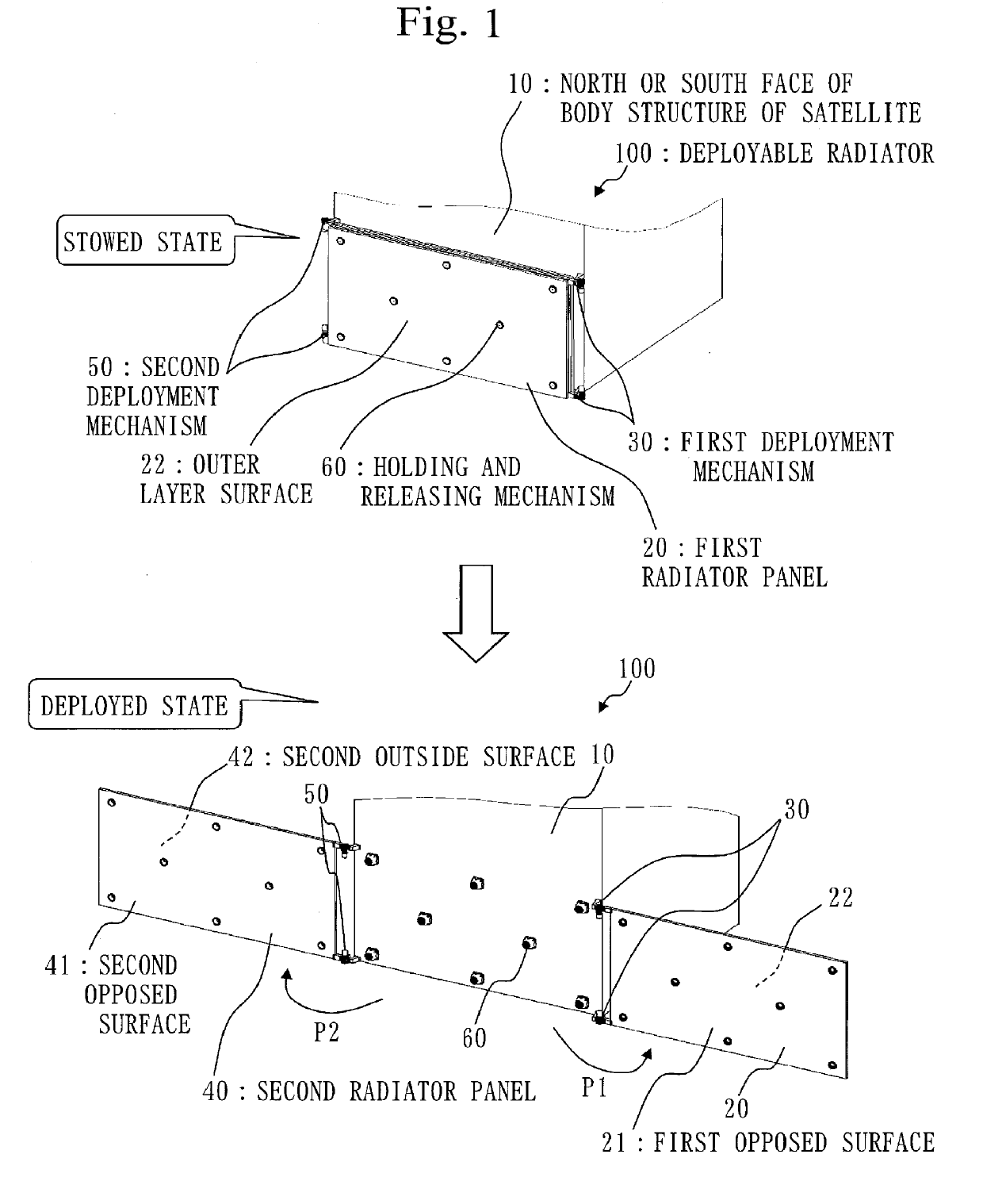
[0030]A configuration of a deployable radiator 100 according to this embodiment will be described, using FIG. 1. FIG. 1 illustrates a stowed state and a deployed state of the deployable radiator 100.

[0031]The deployable radiator 100 is mounted on a north or south face 10 of the body structure of a satellite.

[0032]The deployable radiator 100 includes a first radiator panel 20, a first deployment mechanism 30, a second radiator panel 40, a second deployment mechanism 50, and holding and releasing mechanisms 60.

[0033]Hereinafter, illustration of a flexible tube that connects a steam pipe in the body structure of the satellite and a condenser tube in each radiator panel will be omitted.

[0034]The first radiator panel 20 is deployably connected to the north or south face 10 of the body structure of the satellite by the first deployment mechanism 30.

[0035]The first deployment mechanism 30 connects the first radiator panel 20 to the no...

Example

Second Embodiment

[0053]In this embodiment, a difference from the first embodiment will be mainly described.

[0054]In this embodiment, a same reference numeral is given to a component that is the same as the one described in the first embodiment, and a description of the component may be omitted.

[0055]In this embodiment, a description will be given about a deployable radiator 100a in which, while minimizing spacecraft heat loss during orbit raising, an amount of heat removal after a satellite has reached a geostationary orbit can be more maximized than that in the first embodiment and a mass of the satellite can be minimized.

[0056]***Description of Configuration***

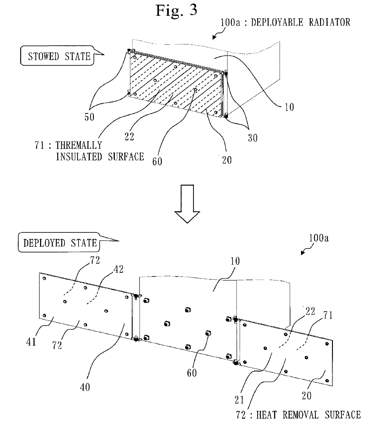
[0057]A configuration of the deployable radiator 100a according to this embodiment will be described, using FIG. 3.

[0058]As illustrated in FIG. 3, the outer layer surface 22 of the first radiator panel 20 becomes an outermost layer surface in a stowed state. Accordingly, in order to minimize the spacecraft heat loss during t...

Example

Third Embodiment

[0087]In this embodiment, a difference from the first embodiment and the second embodiment will be mainly described.

[0088]In this embodiment, a same reference numeral is given to a component that is the same as the component described in the first and second embodiments, and a description of the component may be omitted.

[0089]***Description of Configuration***

[0090]A configuration of a deployable radiator 100b according to this embodiment will be described, using FIG. 4.

[0091]In this embodiment, it is assumed that both surfaces of the first radiator panel 20 and both surfaces of the second radiator panel 40 are the heat removal surfaces 72.

[0092]As illustrated in FIG. 4, the first radiator panel 20 includes a thermally insulated panel 110 that covers at least a portion of the outer layer surface 22 in a state where the first radiator panel 20 is opposed to the north or south face 10 of the body structure of a satellite. The thermally insulated panel 110 is also refer...


PUM

PropertyMeasurementUnit
Structureaaaaaaaaaa
Thermal propertiesaaaaaaaaaa

Abstract

A first deployment mechanism (30) deploys a first radiator panel (20) from a state where the first radiator panel (20) is opposed to a north or south face (10) of the body structure of a satellite. A second radiator panel (40) is stacked with the first radiator panel (20) to be opposed to the north or south face (10) of the body structure of the satellite and is sandwiched between the north and south face (10) of the body structure of the satellite and the first radiator panel (20), in a state where the first radiator panel (20) is opposed to the north or south face (10) of the body structure of the satellite. A second deployment mechanism (50) connects the second radiator panel (40) to the north or south face (10) of the body structure of the satellite, and deploys the second radiator panel (40) in a direction P2 opposite to a deployment direction P1 of the first radiator panel from a state where the second radiator panel (40) is opposed to the north or south face (10) of the body structure of the satellite.

Description

TECHNICAL FIELD[0001]The present invention relates to a deployable radiator that is mounted on a satellite.BACKGROUND ART[0002]In recent years, due to larger power consumption of an artificial satellite, an amount of heat removal from the satellite has steadily been increasing. A heat removal area becomes insufficient just by conventional heat removal from a body structure surface of the satellite, so that it is becoming impossible to ensure a necessary amount of the heat removal. A deployable radiator is applied in order to ensure this necessary heat removal area.[0003]In the deployable radiator, a radiator panel is secured to the body structure surface of the satellite using a holding and releasing mechanism when the satellite is launched. The holding and releasing mechanism releases the radiator panel when the satellite reaches an orbit. After having been released, the radiator panel is deployed by a deployment mechanism, thereby increasing a heat removal area. The radiator panel...

Claims


Application Information

Patent Timeline
IPC IPC(8): B64G1/50B64G1/22B64G1/44B23P15/26
CPCB64G1/503B64G1/44B64G1/506B23P15/26B64G1/58
Inventor KAWAMURA, SHUNICHI
Owner MITSUBISHI ELECTRIC CORP
Why Eureka
Try Eureka