
Method to check the consummation of sampling by concave liquid level

Active Publication Date: 2019-10-31
SHIMADZU CORP
View PDF0 Cites 0 Cited by
  • Summary
  • Abstract
  • Description
  • Claims
  • Application Information

AI Technical Summary

Benefits of technology

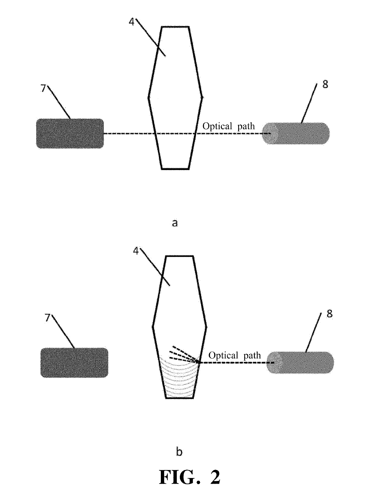
The present invention is a detection system that uses an existing light source and a photoelectric sensor to detect any liquid samples supplied to the system. The system is designed to keep the light source and photoelectric sensor operating while the detection sample is being supplied. When the detection sample reaches the optical path of the detection light, the light is scattered and / or refracted, resulting in a reduction in the intensity of the detection light received by the photoelectric sensor. By monitoring this change in light intensity, the system can easily, reliably, and quickly determine whether or not a detection sample has been supplied. Overall, this technology provides a convenient and efficient way to detect liquid samples in a detection system.

Problems solved by technology

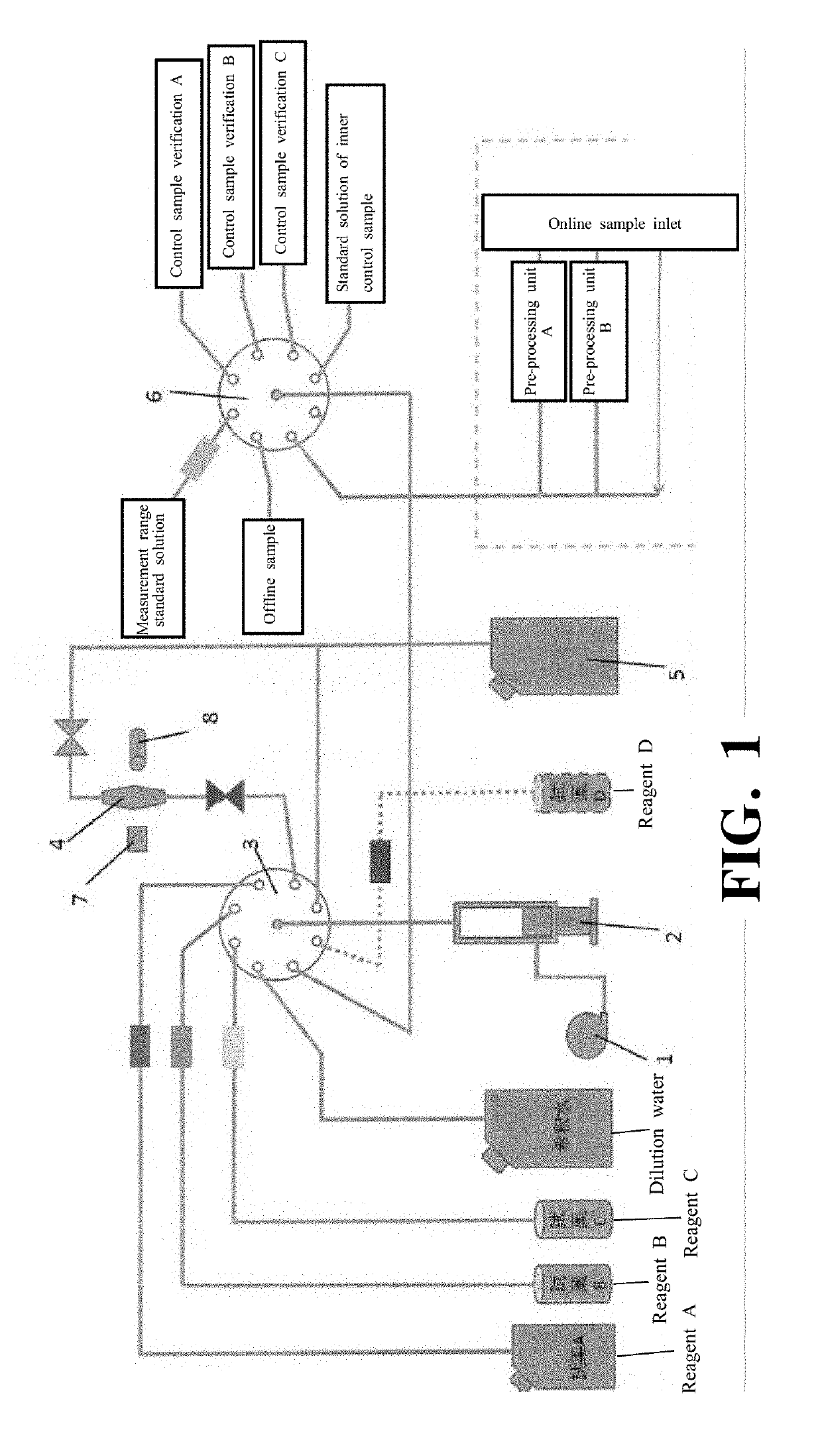
At that time, since it is necessary to add a dilute solution, even if the liquid level exceeds the position of the spectrometer by adding a reagent, it is not possible to judge whether or not the detection sample has been supplied.

Method used


Image

  • Method to check the consummation of sampling by concave liquid level
  • Method to check the consummation of sampling by concave liquid level

Examples


Embodiment Construction

[0013]Hereinafter, embodiments of the present invention will be described with reference to the drawings.

[0014]As shown in FIG. 1, the detection system according to the present invention is provided with an air mixing pump 1, a syringe 2, multi-port valves 3 and 6, a reaction cell 4, a waste bucket 5, a photoelectric sensor 7, a light source 8, and containers storing reagents A to D and dilution water. The photoelectric sensor 7 and the light source 8 are devices provided in an existing spectrometer in a detection system. The photoelectric sensor 7 is configured to receive the detection light transmitted through the reaction cell 4 from the light source 8. Specifically, the light source 8 is configured to emit detection light toward the inside of the reaction cell 4 from one side of the reaction cell 4. The photoelectric sensor 7 is arranged on the other side of the reaction cell 4 so as to face the light source 8, and is configured to receive the detection light transmitted through...


PUM


Abstract

A detection system may include a reaction cell which is a container for reacting the detection sample, a light source configured to emit a detection light toward an inside of the reaction cell from one side of the reaction cell, and a photoelectric sensor arranged on the other side of the reaction cell so as to face the light source and configured to receive the detection light transmitted through the reaction cell and convert a signal of the received detection light into an electrical signal. A judging method may include judging whether or not the detection sample has been supplied based on whether or not the electrical signal output from the photoelectric sensor changes by sending an instruction to supply the detection sample to the reaction cell to the detection system in a state in which the light source and the photoelectric sensor are kept being operated. When the liquid level of the detection sample reaches an optical path of the detection light and an amount of change of the electrical signal output from the photoelectric sensor exceeds a specified threshold, it may be judged that the detection sample has been supplied. According to embodiments of the present invention, it is possible to easily, assuredly and quickly judge whether or not the detection sample has been supplied by existing devices in a detection system.

Description

TECHNICAL FIELD[0001]The present invention relates to a method for judging whether or not a detection sample has been supplied.BACKGROUND ART[0002]In a detection system, it is necessary to judge whether or not a detection sample has been supplied for the purpose of preventing occurrence of detection errors and / or a waste of resources due to false detection or the like. Further, in a detection system, such as a real-time environment monitoring system, configured to perform real-time online detection of a detection sample, in order to quickly judge whether or not a malfunction occurred in the sampling system, it is necessary to judge whether or not an online sample has been sampled.[0003]The above-described detection system is provided with, as major components, a reaction cell, a sample supply unit, reagent supply units, and a spectrometer (light source, photoelectric sensor). In the reaction cell, a sample reacts with a reagent and the reacted sample is detected. Thus, a detection r...

Claims


Application Information

Patent Timeline
IPC IPC(8): G01N35/10G01F23/292
CPCG01F23/292G01N2001/002G01N35/1009G01N2035/1025G01V8/12G01F23/2921
Inventor GU, TINGHUANG, HONGYIXU, CHAO
Owner SHIMADZU CORP
Learn More