System and method of displaying images

Inactive Publication Date: 2005-02-15
TP VISION HLDG B V HOLDCO
View PDF14 Cites 40 Cited by
  • Summary
  • Abstract
  • Description
  • Claims
  • Application Information

AI Technical Summary

Benefits of technology

It is an object of the invention to provide a system of the type described in the opening paragraph, in which the light intensity can be reduced independently of the intensity of the image signal for given parts of the image which may reduce the lifetime of a display tube. To this end, the system according to the invention, is characterized in that the system is further provided with a motion detector for detecting motion in a stationary part within the area, and in that the reduction means reduces the light intensity of the stationary part within the area when motion has also been detected with

Problems solved by technology

A stationary part, such a logo, may be harmful if it is presen

Method used


Image

  • System and method of displaying images
  • System and method of displaying images
  • System and method of displaying images

Examples


Example

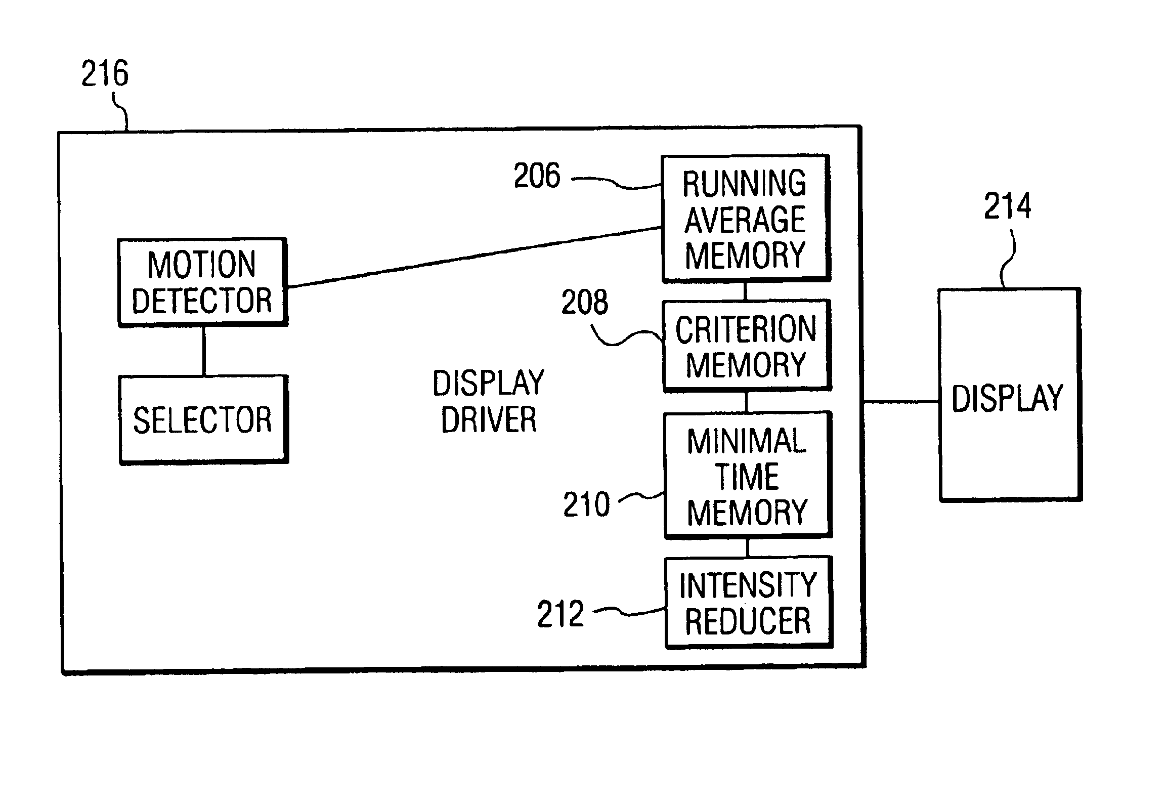
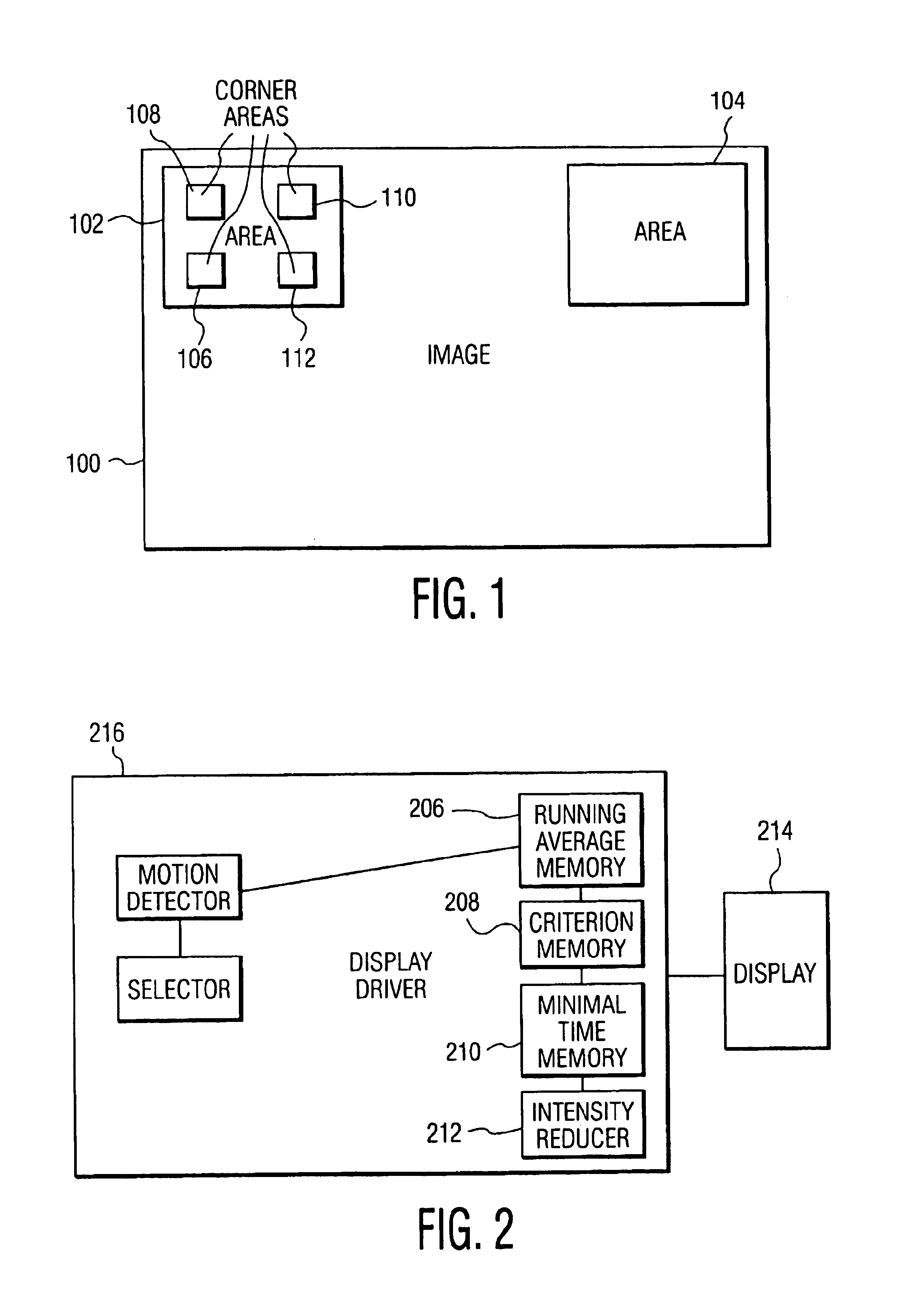
FIG. 1 shows an example of a display screen displaying an image 100 showing positions of areas 102 and 104 within which the intensity can be reduced. Stationary objects, such as logos, are often displayed in a corner of the image because they cover the image at that area to a minimal extent. To be able to detect these logos, it is useful to search for stationary object in the corners of the image. The areas 102 and 104 are therefore positioned in the corners of the image 100 but, in principle, they may be positioned anywhere on the image or even move across the image and regularly reach a different position. Furthermore, logos are generally not so large: on a 28 inch display, they are often smaller than 3-by-3 cm. It is thus sufficient to search for motion in relatively small areas of, for example, 50-by-50 pixels. The number of areas within which logos can be detected may vary. For example, the image may be entirely divided into small areas within which motion is searched. The area...


PUM


Abstract

Logos may be present in images transmitted by television stations. These logos are often present in the corners (102, 104) of an image (100) for a long time. They do not move and may comprise saturated colors. This results in burn-in effects in emissive displays because the logos provide the same display load at the same location for a relatively long period of time. The burn-in effect can be prevented by detecting the logos in the corners (102, 104) of the image (100) and reducing their intensity to the average display load.

Description

BACKGROUND OF THE INVENTION1. Field of the InventionThe invention relates to a system for displaying an image, the system being provided with selection means for selecting an area within the image, and reduction means for reducing a light intensity of the image.The invention also relates to a method of displaying an image, the method comprising the steps of selecting an area within the image, and reducing the light intensity of the image.2. Description of the Related ArtSuch a system and method are known from European Patent Application No. EP-B-0 589 513, corresponding to U.S. Pat. No. 5,349,390, describing a number of light intensity-reducing functions protecting the processors and the display tube of television receivers from overload. The image quality is enhanced by these functions and the lifetime of the display tube is extended. A first light intensity-reducing function acts on larger areas, such as persons' faces, and is performed when the period during which the image signa...

Claims


Application Information

Patent Timeline
IPC IPC(8): H04N5/57H04N5/14H04N5/445H04N5/68G09G1/00G09G5/00G09G5/10
CPCH04N5/144H04N5/57H04N21/485H04N5/68H04N21/4318H04N21/44008
Inventor HOLTSLAG, ANTONIUS HENDRICUS MARIA
Owner TP VISION HLDG B V HOLDCO
Why Eureka
Try Eureka