Liquid ejecting apparatus, liquid filling method, and air bubble discharging method
- Summary
- Abstract
- Description
- Claims
- Application Information
AI Technical Summary
Benefits of technology
Problems solved by technology
Method used
Image
Examples
first embodiment
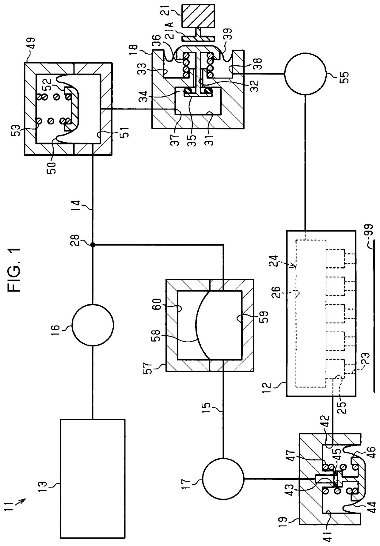
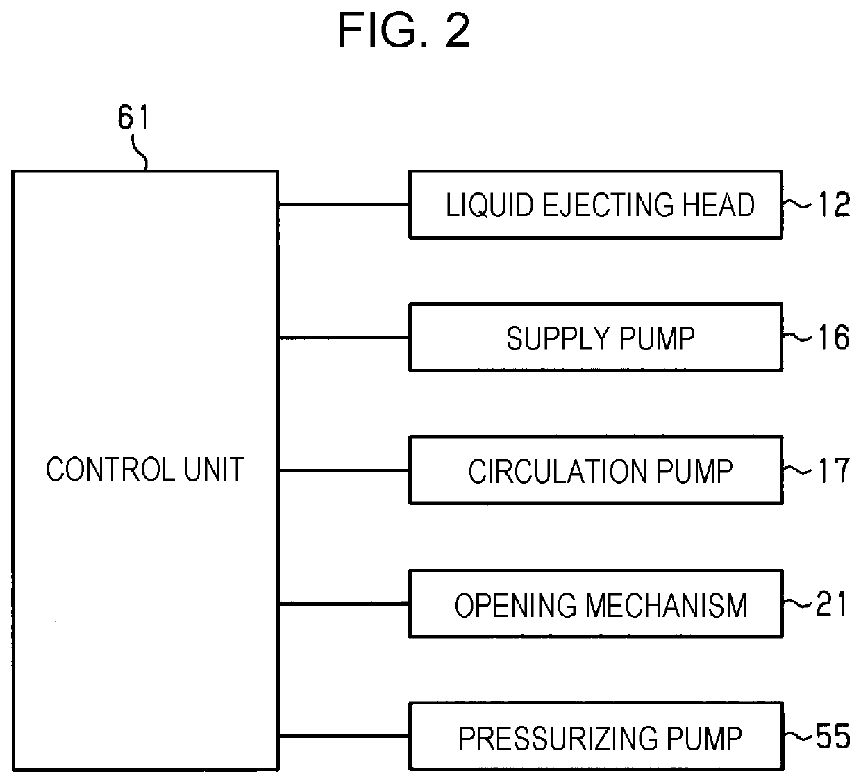
[0020]As shown in FIG. 1, a liquid ejecting apparatus 11 includes a liquid ejecting head 12 that ejects liquid, a supply flow path 14 for supplying liquid from a liquid supply source 13 to the liquid ejecting head 12, and a first circulation flow path 15 for circulating liquid. The liquid ejecting apparatus 11 includes a supply pump 16 that supplies liquid via the supply flow path 14, and a circulation pump 17 that circulates liquid via the first circulation flow path 15. The liquid ejecting apparatus 11 includes a first pressure regulating valve 18 that adjusts pressure in the supply flow path 14, and a second pressure regulating valve 19 that adjusts pressure in the first circulation flow path 15. The liquid ejecting apparatus 11 includes an opening mechanism 21 configured to forcibly open the first pressure regulating valve 18.
[0021]The liquid ejecting head 12 has one or more nozzles 23. The liquid ejecting head 12 has a liquid chamber 24 which communicates with the nozzles 23. T...
second embodiment
[0077]Next, a second embodiment of the liquid ejecting apparatus 11 will now be described. The liquid ejecting apparatus 11 of the second embodiment has the same configuration as that of the liquid ejecting apparatus 11 of the first embodiment except for the configuration of the buffer 49 and the defoaming portion 57. Therefore, in the second embodiment, differences in configuration will be mainly described.
[0078]As shown in FIG. 5, the liquid ejecting apparatus 11 of the second embodiment includes a buffer 63 configured to store liquid. The buffer 63 is located between the first connecting section 28 and the first pressure regulating valve 18 in the supply flow path 14. The buffer 63 includes a buffer chamber 64 for storing liquid. The buffer chamber 64 is located in the middle of the supply flow path 14. As liquid is stored in the buffer chamber 64, air bubbles rise up in the stored liquid and accumulate in an upper space in the buffer chamber 64. Thus, the buffer 63 captures air ...
third embodiment
[0090]Next, a third embodiment of the liquid ejecting apparatus 11 will now be described. The liquid ejecting apparatus 11 of the third embodiment has the same configuration as that of the liquid ejecting apparatus 11 of the first embodiment except for having a second circulation flow path. Therefore, in the third embodiment, differences in configuration will be mainly described.
[0091]As shown in FIG. 8, the liquid ejecting apparatus 11 of the third embodiment includes a second circulation flow path 68 for circulating liquid, and a third pressure regulating valve 69 that adjusts pressure in the second circulation flow path 68. A first end of the second circulation flow path 68 is connected to a second connecting section 70, which is provided downstream relative to the supply pump 16 in the supply flow path 14. A second end of the second circulation flow path 68 is connected to a third connecting section 71, which is provided upstream relative to the supply pump 16 in the supply flow...
PUM
 Abstract
Description
Claims
Application Information
 - R&D
- Intellectual Property
- Life Sciences
- Materials
- Tech Scout
- Unparalleled Data Quality
- Higher Quality Content
- 60% Fewer Hallucinations
Browse by: Latest US Patents, China's latest patents, Technical Efficacy Thesaurus, Application Domain, Technology Topic, Popular Technical Reports.
© 2025 PatSnap. All rights reserved.Legal|Privacy policy|Modern Slavery Act Transparency Statement|Sitemap|About US| Contact US: help@patsnap.com


