
Radial rolling bearing especially double-row angular contact bearing

Inactive Publication Date: 2010-11-25
SCHAEFFLER TECH AG & CO KG
View PDF16 Cites 3 Cited by
  • Summary
  • Abstract
  • Description
  • Claims
  • Application Information

AI Technical Summary

Benefits of technology

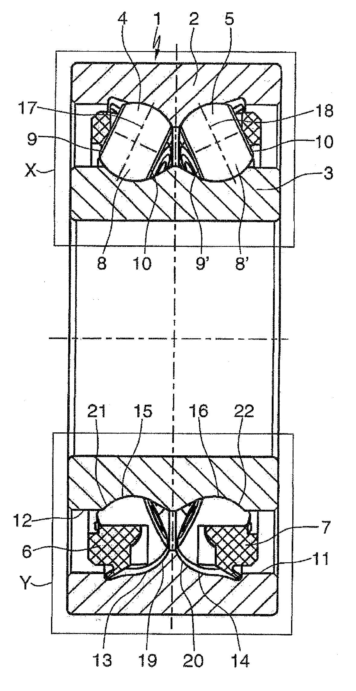
[0007]Accordingly, according to claim 2, there is provision in the radial rolling bearing according to the invention that it is preferably embodied as a double-row angular contact rolling bearing with contact angle axes which are positioned in an O arrangement with respect to one another, in which radial rolling bearing both rows of the rolling bodies are embodied as ball rollers and all the raceways in the bearing rings are embodied with additional free space contours and supporting contours in the region of the edge parts lying opposite the shoulders of said raceways. As a result, a symmetrical embodiment of the bearing rings is advantageously obtained, which embodiment has a favorable effect on the fabrication costs of said bearing rings. However, it is also possible to fill the angular contact rolling bearing with a row of ball rollers and a row of bearing balls which are then firstly mounted in the inner bearing ring without an outer bearing ring, in order subsequently to fit the outer bearing ring onto the bearing balls and finally insert the ball rollers into the bearing in the described way.
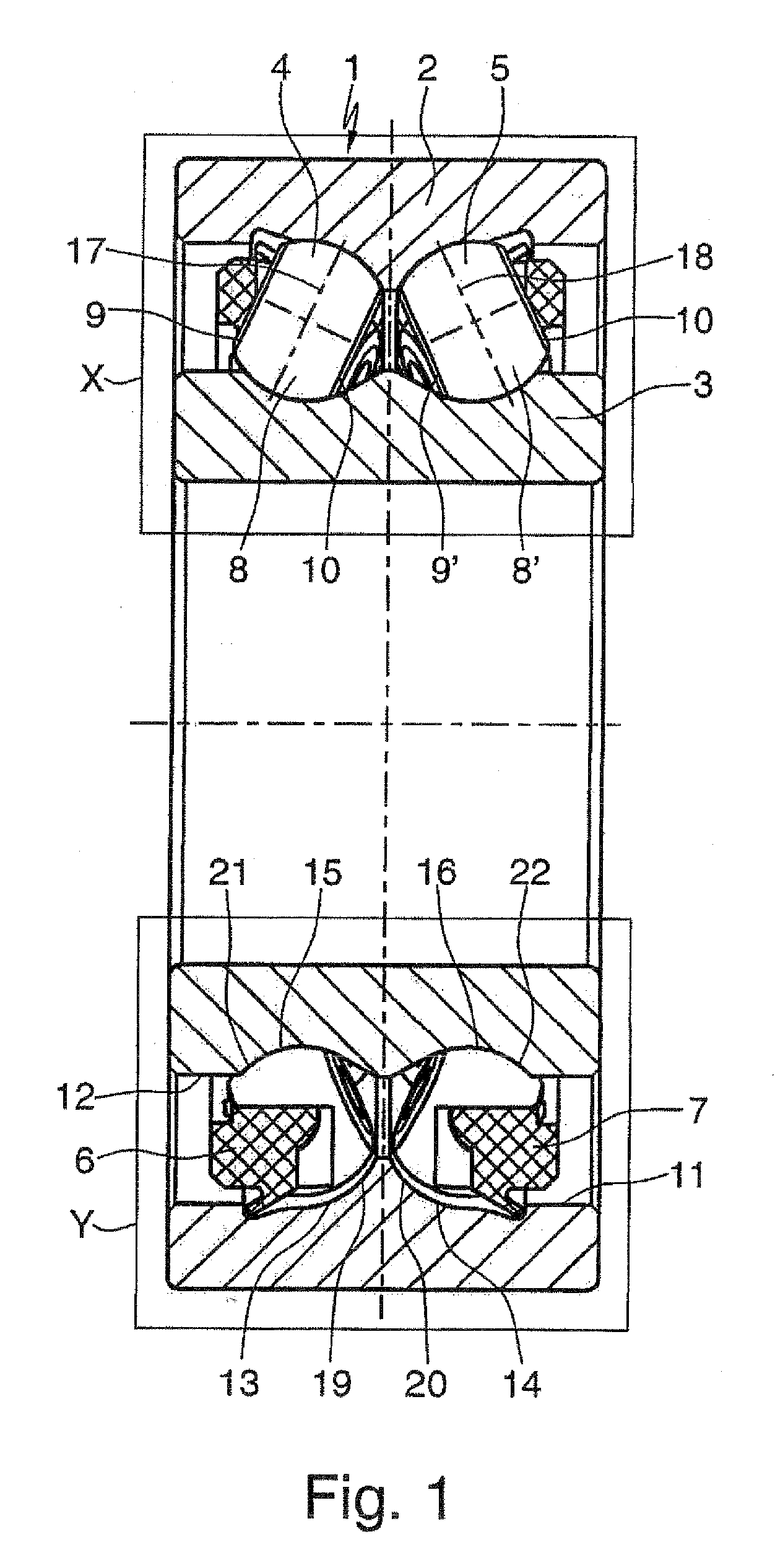
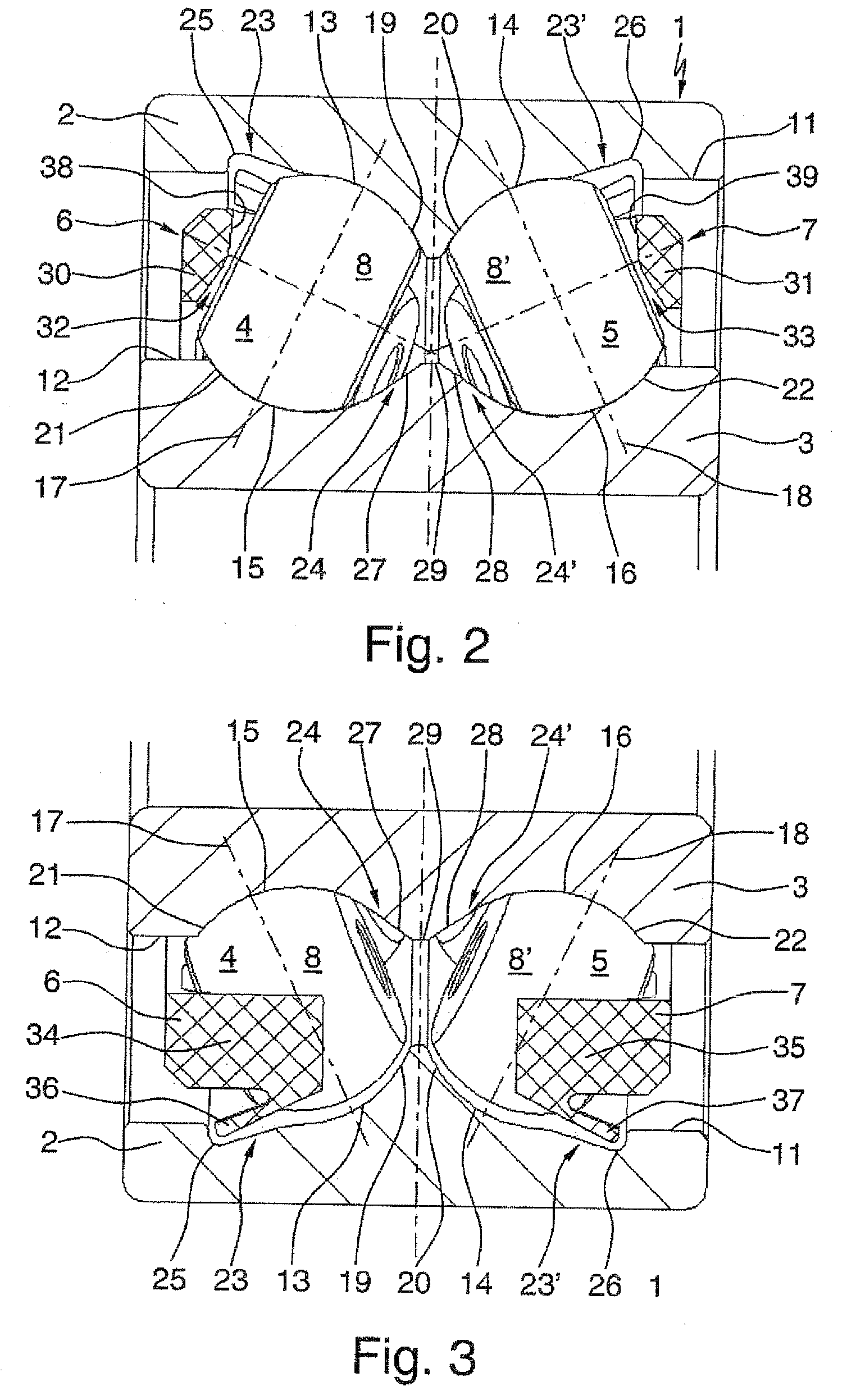
[0008]Starting from the features of claim 2, a further feature of the radial rolling bearing embodied according to the invention as claimed in claim 3, is that annular grooves which, in the outer bearing ring, in each case open into raceways thereof, and are wedge-shaped in cross-section, are arranged as additional free space contours which are provided in order to bring about the necessary freedom of movement in order to tilt the ball rollers into their operating position in the raceways of the two bearing rings. These wedge-shaped annular grooves are each formed with their wedge face which opens into the raceways in the outer bearing ring extending obliquely with respect to the axial sides of the radial rolling bearing, in the inner side of the outer bearing ring, and each have, together with the adjoining raceway, a somewhat greater length than the diameter of the ball rollers and a depth which is dependent on the contact angle of the bearing and is proportionally larger as the contact angle increases. The annular grooves which are embodied in such a way therefore provide the necessary free space in order to avoid the misalignment, described in the prior art, of the ball rollers with their side faces on the inner side of the outer bearing ring when the tilting into their raceways is initiated.
[0009]According to claim 4, the rolling bearing which is embodied according to the invention is also distinguished by the fact that, arranged as an additional supporting contour in the inner bearing ring is a central rim, which is wedge-shaped in cross-section, opens in each case with its wedge faces into the raceways of said bearing ring and is provided for carrying out pivoting guidance during the tilting of the ball rollers into their operating position in the raceways of the two bearing rings. This wedge-shaped central rim is here approximately of the same height as the shoulders on the raceways of the inner bearing ring and has, between its wedge faces, an angle which is dependent on the distance between the raceways in the inner bearing ring. With the aid of a central rim which is embodied in such a way it is therefore possible to prevent the ball rollers from slipping through between the bearing rings in the direction of the raceway lying respectively opposite in the inner bearing ring, as described in the prior art, and to avoid the renewed misalignment of the ball rollers on the raceway provided for them in the inner bearing ring, as well as to support the ball rollers during the tilting into their raceways on their pivoting path until they have reached their final operating position in the raceways.
[0013]Finally, it is additionally proposed in claim 7 that the base of all the cage pockets in the bearing cages are additionally embodied in a slight roof-shape in order to automatically adapt the rolling bodies, formed as ball rollers, to operationally conditioned fluctuations in the contact angle axes in the circumferential direction. “In a slight roof-shape” is to be understood here as meaning that the base of the cage pockets which is embodied in an oblique fashion and id already adapted to the contact angle of the radial rolling bearing additionally has, in the circumferential direction, a uniform, wedge-shaped elevation in the form of a roof whose slope is approximately 5° to 10° on both sides. As a result it is possible for the ball rollers to adapt themselves automatically in their pockets to contact angle fluctuations between 10° and 20° without the ball rollers snapping out of their cage pockets in the process.
[0014]To summarize, the radial rolling bearing embodied according to the invention therefore has the advantage over the radial rolling bearings known from the prior art that, as a result of the embodiment with additional free space contours and supporting contours on the raceways of the rolling bodies in the inner bearing ring and in the outer bearing ring, said radial rolling bearing can easily be filled, in the axial mounting procedure, with rolling bodies which are embodied as ball rollers. At the same time, the embodiment of the bearing cages in the two rows of ball rollers as collar snap-action cages with collars which are made extremely narrow at the pitch circle and with all the cage pockets having a base which is embodied in the form of a roof ensures that the highest possible degree of filling of the angular contact rolling bearing occurs and the ball rollers can be adapted to operationally conditioned fluctuations in the contact angle axes.

Problems solved by technology

However, in practice it has been found that with a double-row angular contact rolling bearing which is embodied in such a way it is not possible to mount the ball rollers in the described manner, or it is only possible to do so with very high expenditure.
When attempting to perform such mounting of the ball rollers it has, in fact, become apparent that after the ball rollers have been inserted axially into the clearance between the bearing rings until they abut against their raceway in the outer bearing ring, it is not possible to tilt the ball rollers in the direction of the raceways in the inner bearing ring or it is only possible to do so with large application of force, since the latter become misaligned with their side faces pointing to the outer bearing ring on the inner side of the outer bearing ring.
Even if it is then possible to tilt the ball rollers in the direction of the raceways in the inner bearing ring while using tolerances or the elasticity of all the parts, the limits of the specified mounting possibility are run up against once more since the ball rollers frequently slip through between the bearing rings in the direction of the raceway lying opposite in the inner bearing ring, or the ball rollers become misaligned again on the raceway provided for them in the inner bearing ring.
Furthermore, it has proven a disadvantage of the described bearing cage for the double-row angular contact rolling bearing that the pocket webs which are embodied with the snap-action projections are of relatively broad design and therefore do not constitute an optimum for the largest possible degree of filling of the angular contact rolling bearing.
It is also disadvantageous that the possibility of movement of the ball rollers in the pockets of the snap-action cage cannot be adapted to operationally conditioned fluctuations in the contact angle axes, with the result that when such fluctuations in the contact angle occur it is very probable that the ball rollers will snap out of their cage pockets and as a result serious damage will occur to the bearing.

Method used


Image

  • Radial rolling bearing especially double-row angular contact bearing
  • Radial rolling bearing especially double-row angular contact bearing
  • Radial rolling bearing especially double-row angular contact bearing

Examples


Embodiment Construction

[0005]According to the invention, this object is achieved in a double-row angular contact rolling bearing having at least one row of ball rollers according to the preamble of claim 1, in that, on the one hand, additional free space contours and supporting contours are integrally formed at least on the raceways, arranged in the outer bearing ring and in the inner bearing ring of the row of rolling bodies which are embodied as ball rollers, in each case in the region of the axial edge parts lying opposite the shoulders of said raceways, by means of which free space contours and supporting contours the ball rollers can be fitted into the angular contact rolling bearing through axial insertion into the clearance between the bearing rings and subsequent tilting into the raceways.

[0006]Preferred embodiments and developments of the radial roiling bearing embodied according to the invention are described in the subclaims.

[0007]Accordingly, according to claim 2, there is provision in the rad...


PUM


Abstract

A double-row angular contact bearing and which has outer and inner bearing rings with two rows of rolling elements disposed between the bearing rings that are held by two bearing cages interspaced at even distances. At least one row is configured as balls with parallel lateral faces that are symmetrically flattened. Both rows of rolling elements roll in adjacent races machined into the inner face of the outer ring and the outer face of the inner ring. The contact angle axes are pitched towards each other in an O-arrangement or X-arrangement and the races are axially delimited only on one side by shoulders. Additional clearance and supporting contours are formed at axial edge sections, opposite the shoulders, onto the races. The contours can be used to fit the balls into angular contact by axially inserting them into the clearance between the bearing rings and then tilting them into the races.

Description

FIELD OF THE INVENTION[0001]The invention relates to a radial rolling bearing according to the preamble-forming features of patent claim 1, and said invention can be applied particularly advantageously to double-row angular contact rolling bearings whose rolling bodies are embodied as ball rollers with, in each case, two side faces which are flattened symmetrically from a basic bail shape and are arranged parallel to one another.BACKGROUND OF THE INVENTION[0002]Double-row angular contact rolling bearings are applied wherever not only large radial forces but also large axial forces have to be taken up from both directions due to the bearing position. The most common embodiment of such angular contact rolling bearings in this context is the double-row angular contact rolling bearing in which both rows of bearing balls are arranged on contact angle axes which are positioned in an O-arrangement or X-arrangement with respect to one another. In order to bring about a high level of filling...

Claims


Application Information

Patent Timeline
IPC IPC(8): F16C43/06
CPCF16C19/38F16C33/49F16C43/06F16C33/36F16C2300/02
Inventor BOHR, ANDREASDOEPPING, HORSTHOFMANN, HEINRICH
Owner SCHAEFFLER TECH AG & CO KG
Learn More